On analogplanet.com you'll find coverage of my visit in November 2013 to the 10th annual Manila Hi-Fi Show, which took place the weekend of the devastating typhoon Haiyan (Filipinos call it Yolanda). Because the people I met there are such big Stereophile fans, I wanted to be sure to give them a shout-out in this column, too.
Despite the weather, which prevented audiophiles living on other islands of the archipelago from flying in for the event, at least 2000 managed to attend. These are passionate, enthusiastic audiophiles—and the high proportion of young people, particularly among the vinyl buyers, was encouraging.
The greeting I received throughout the show was beyond my most vivid egomaniacal daydreams. I was treated so well that I don't know how to express my gratitude, other than to just say "Thanks"—and get back to work.
Acoustical Systems SMARTractor cartridge-alignment tool
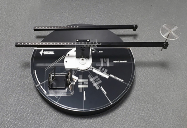
Dietrich Brakemeier's new SMARTractor, from Acoustical Systems in Germany (footnote 1), is easily the most ambitious, well-conceived, well-executed alignment protractor I've seen. At $650, it's also the most expensive. But as I tell vinyl enthusiasts hesitant to drop $300 on a digital microscope, if you've invested thousands of bucks in a cartridge and much more than that in a turntable, don't you want to at least inspect what you bought, not to mention correctly set the stylus rake angle (SRA), overhang, and zenith angle? The SMARTractor promises the greatest accuracy of cartridge alignment ever, along with the ability to easily try a variety of different alignments. While it's true that any alignment curve is, by definition, a compromise, that doesn't mean we shouldn't try to accurately establish our compromises! The heart of the SMARTractor is a semicircle of mirrored plastic, into which are etched five single-point alignment grids: Löfgren A/Baerwald IEC, Löfgren A/Baerwald DIN, Löfgren B/IEC, Löfgren B/DIN, and UNI-DIN, along with a sixth position labeled UNI-P2S, the last three characters standing for "pivot to spindle" distance.
Each alignment option has its own tiny dimple, into which the stylus must fit for the alignment to be perfect. Some users are uncomfortable with such dimples, as well as with the creviced arcs found on similar mirrored alignment devices, such as the Wally Tools WallyTractor. They object that if you're not very careful, you could rip the stylus out of the cantilever—and even if you are careful, you risk putting unnecessary stress on the stylus/cantilever join.
Having installed more cartridges than most, with both the WallyTractor and now the SMARTractor, I've learned that you must first secure the platter to ensure that it can't move, and then, of course, exercise great care during the entire installation process—but you're going to do that anyway, right? To fix the platter in place, use a rubber wedge or whatever you've got handy, and you'll be okay. The advantage of a creviced arc or dimple is that it leaves no room for error or judgment calls: You're in or you're out.
The dimple is just one of many features Brakemeier has designed into the SMARTractor to ensure its accuracy. Most cartridge aligners based on the spindle have oversize holes to ensure compatibility with the wide range of spindle diameters. Brakemeier includes three pop-in spindle adapters (7.1, 7.15, and 7.2mm thick), to ensure that spindle play will produce no error.
 The second major component of the SMARTractor is a complex assembly that rotates around the spindle. Into one of five small, threaded holes in the semicircular mirror, the user inserts a screw with a knurled plastic head, to lock the assembly into the proper position for one of the five alignment geometries.
The assembly includes two key parts: a clear plastic wing, at its center a large square cutout; and a black, vertical polyoxymethylene (POM) structure that holds the pivot-to-spindle and alignment beam. When you rotate the assembly, the wing rotates just above the semicircle's surface; when it locks in place, it "squares" with the corresponding alignment grid.
The alignment beam has a precision vernier scale accurate to a 5/100th value. If your arm's pivot-to-spindle distance is 221.7mm, like my Continuum Cobra's, you don't have to estimate the final "0.7mm." It can be set ultra-precisely, which is particularly useful with sliding arm mounts or for ultraprecise drilling of armboards. The Cobra's pivot-to-spindle distance can be tweaked; using the SMARTractor, I was able to improve on its previously locked P2S distance.
Some tonearms have a mark or dimple to delineate the horizontal pivot point, which makes it easy to position the alignment beam before setting the cartridge overhang. Some arms, such as those made by Rega Research, make this setting notoriously difficult.
The SMARTractor's alignment-beam pin is topped by a clear plastic disc, into which is etched a reticle scale (think of the markings on a periscope's lens). If you can look down from directly above at the unmarked bearing of, say, a Rega arm, you can use the SMARTractor's pattern to center the locator pin. This will get much closer to the bearing's actual position than any method of eyeballing I've ever used.
There's another really useful feature. If your tonearm is unusually tall (eg, the Kuzma 4Point), and you've tried using a device like the Dr. Feickert Analogue Protractor NG, you may have found that the alignment beam can't clear the top of the arm's pivot point, rendering the protractor unusable. The SMARTractor includes a set of POM extender posts that raise the alignment beam's height. With these installed, the beam easily cleared the 4Point's vertical-tracking-angle (VTA) tower and reached the pivot.
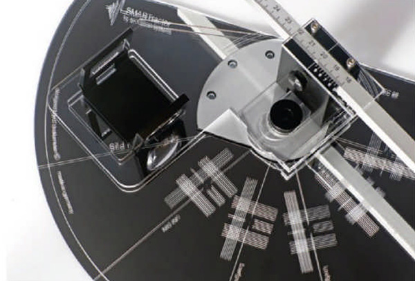
The SMARTractor's sighting and magnification system are as well thought out, precise, and useful as everything so far described. The included magnifying glass (made of glass, not plastic) is set in a heavy, hinged, three-piece metal frame, the central section of which sits in the square cutout of the clear plastic wing. The cutout is wide enough to allow it to be aligned with the center of the grid. White lines surrounding the frame opposite the magnifying glass aid in setting precise parallax, to help ensure that you're viewing the cantilever from directly in front, which in turn helps you correctly set the stylus's zenith angle.
Using the SMARTractor: Choose the correct spindle adapter, pop it into the mirrored semicircle, remove the thumbscrew, rotate the assembly to the desired alignment geometry, slide the mechanism fore and aft until the holes line up, and reinsert the thumbscrew. Put the stainless-steel pin in the alignment beam and lock it in place, loosen the alignment beam's thumbscrew, move the beam outward toward the arm pivot, and lower the pin onto the center of the bearing point (if visible; if it isn't, follow the outlined reticle procedure). Hopefully, the vernier-scale measurement will match the pivot-to-spindle distance specified for your tonearm. The SMARTractor can be used with tonearms with specified pivot-to-spindle distances of up to 315mm.
Stop both the platter and the SMARTractor from turning (painter's tape works well and leaves no residue). Then, after installing the cartridge and setting the vertical tracking force (VTF), lower the stylus onto the mirror, as close as possible to the dimple. Put the magnifying glass in the cutout and adjust its angle until the dimple comes into sharp focus.
Only at this point will you be able to fully appreciate the effectiveness of the SMARTractor's design. Because of the magnifying glass's adjustability and its considerable depth of field, even cartridges with "hidden" cantilevers should be easy to align. Once you've adjusted the cartridge's position in the headshell so that the stylus seems to be resting in the dimple, it's a good idea to confirm this by looking at the stylus from the side, using a second loupe. That done, look at the cartridge directly from the front, to make sure the parallax is perfect; if necessary, adjust the zenith angle.
The parallel grid lines on either side of the cantilever will help proper setting, but so will the cantilever's reflection in the mirror. The result should be a straight line similar to the one that used to be considered correct for setting the azimuth angle.
When the zenith angle has been set and the stylus is still in the dimple, tighten the cartridge screws evenly, a little at a time on either side. You're done.
The second major component of the SMARTractor is a complex assembly that rotates around the spindle. Into one of five small, threaded holes in the semicircular mirror, the user inserts a screw with a knurled plastic head, to lock the assembly into the proper position for one of the five alignment geometries.
The assembly includes two key parts: a clear plastic wing, at its center a large square cutout; and a black, vertical polyoxymethylene (POM) structure that holds the pivot-to-spindle and alignment beam. When you rotate the assembly, the wing rotates just above the semicircle's surface; when it locks in place, it "squares" with the corresponding alignment grid.
The alignment beam has a precision vernier scale accurate to a 5/100th value. If your arm's pivot-to-spindle distance is 221.7mm, like my Continuum Cobra's, you don't have to estimate the final "0.7mm." It can be set ultra-precisely, which is particularly useful with sliding arm mounts or for ultraprecise drilling of armboards. The Cobra's pivot-to-spindle distance can be tweaked; using the SMARTractor, I was able to improve on its previously locked P2S distance.
Some tonearms have a mark or dimple to delineate the horizontal pivot point, which makes it easy to position the alignment beam before setting the cartridge overhang. Some arms, such as those made by Rega Research, make this setting notoriously difficult.
The SMARTractor's alignment-beam pin is topped by a clear plastic disc, into which is etched a reticle scale (think of the markings on a periscope's lens). If you can look down from directly above at the unmarked bearing of, say, a Rega arm, you can use the SMARTractor's pattern to center the locator pin. This will get much closer to the bearing's actual position than any method of eyeballing I've ever used.
There's another really useful feature. If your tonearm is unusually tall (eg, the Kuzma 4Point), and you've tried using a device like the Dr. Feickert Analogue Protractor NG, you may have found that the alignment beam can't clear the top of the arm's pivot point, rendering the protractor unusable. The SMARTractor includes a set of POM extender posts that raise the alignment beam's height. With these installed, the beam easily cleared the 4Point's vertical-tracking-angle (VTA) tower and reached the pivot.
The SMARTractor's sighting and magnification system are as well thought out, precise, and useful as everything so far described. The included magnifying glass (made of glass, not plastic) is set in a heavy, hinged, three-piece metal frame, the central section of which sits in the square cutout of the clear plastic wing. The cutout is wide enough to allow it to be aligned with the center of the grid. White lines surrounding the frame opposite the magnifying glass aid in setting precise parallax, to help ensure that you're viewing the cantilever from directly in front, which in turn helps you correctly set the stylus's zenith angle.
Using the SMARTractor: Choose the correct spindle adapter, pop it into the mirrored semicircle, remove the thumbscrew, rotate the assembly to the desired alignment geometry, slide the mechanism fore and aft until the holes line up, and reinsert the thumbscrew. Put the stainless-steel pin in the alignment beam and lock it in place, loosen the alignment beam's thumbscrew, move the beam outward toward the arm pivot, and lower the pin onto the center of the bearing point (if visible; if it isn't, follow the outlined reticle procedure). Hopefully, the vernier-scale measurement will match the pivot-to-spindle distance specified for your tonearm. The SMARTractor can be used with tonearms with specified pivot-to-spindle distances of up to 315mm.
Stop both the platter and the SMARTractor from turning (painter's tape works well and leaves no residue). Then, after installing the cartridge and setting the vertical tracking force (VTF), lower the stylus onto the mirror, as close as possible to the dimple. Put the magnifying glass in the cutout and adjust its angle until the dimple comes into sharp focus.
Only at this point will you be able to fully appreciate the effectiveness of the SMARTractor's design. Because of the magnifying glass's adjustability and its considerable depth of field, even cartridges with "hidden" cantilevers should be easy to align. Once you've adjusted the cartridge's position in the headshell so that the stylus seems to be resting in the dimple, it's a good idea to confirm this by looking at the stylus from the side, using a second loupe. That done, look at the cartridge directly from the front, to make sure the parallax is perfect; if necessary, adjust the zenith angle.
The parallel grid lines on either side of the cantilever will help proper setting, but so will the cantilever's reflection in the mirror. The result should be a straight line similar to the one that used to be considered correct for setting the azimuth angle.
When the zenith angle has been set and the stylus is still in the dimple, tighten the cartridge screws evenly, a little at a time on either side. You're done.
 Which Alignment Curve?
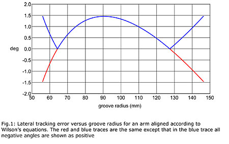
This is where the compromises and controversies come in. Tonearm geometries vary, and so do lead-in and lead-out groove areas. Both the International Electrotechnical Commission (IEC) and the German Institute for Standardization (DIN) have established standards for maximum and minimum modulated groove radii, but have you noticed anyone actually adhering to any standards? In fact, the IEC has set standards more than once, but most agree on a lead-in groove radius of 146mm (maximum distance from the center of the spindle) and a lead-out groove radius of 56mm (minimum distance from spindle). Calculations of distortion and overhang geometry are based on static targets, but the fact is—as a glance at your LPs will tell you—the targets move, almost record by record. If you want to dig deeply into this subject, read Keith Howard's excellent "Arc Angles: Optimizing Tonearm Geometry," in the March 2010 issue. Most interesting is his observation that the distortion caused by lateral tracking error is 2.5 times greater in the inner-groove than the outer-groove area, because of the decreasing speed of linear travel at which the groove passes the stylus—even when the angular error remains constant. Another point to ponder in Howard's piece is that the angular distortion we seek to minimize affects only the stereo groove's lateral, not its vertical modulation, meaning it will be most audible toward the center of the soundstage. Vertical modulation distortion is caused by a tracking error resulting from improperly set SRA and VTA that will affect playback of the entire side, which is why I recommend setting SRA and VTA using a USB microscope.
Footnote 1: Acoustical Systems, Web: www.arche-headshell.de. US Distributor: VANA Ltd. Mukilteo, WA 98275 (2014). Matterhorn Distribution, Covina, CA (2025). Tel: (626) 966-6259. Email: matterdistro@gmail.com. Web: www.matterdistro.com.
Dietrich Brakemeier's new SMARTractor, from Acoustical Systems in Germany (footnote 1), is easily the most ambitious, well-conceived, well-executed alignment protractor I've seen. At $650, it's also the most expensive. But as I tell vinyl enthusiasts hesitant to drop $300 on a digital microscope, if you've invested thousands of bucks in a cartridge and much more than that in a turntable, don't you want to at least inspect what you bought, not to mention correctly set the stylus rake angle (SRA), overhang, and zenith angle? The SMARTractor promises the greatest accuracy of cartridge alignment ever, along with the ability to easily try a variety of different alignments. While it's true that any alignment curve is, by definition, a compromise, that doesn't mean we shouldn't try to accurately establish our compromises! The heart of the SMARTractor is a semicircle of mirrored plastic, into which are etched five single-point alignment grids: Löfgren A/Baerwald IEC, Löfgren A/Baerwald DIN, Löfgren B/IEC, Löfgren B/DIN, and UNI-DIN, along with a sixth position labeled UNI-P2S, the last three characters standing for "pivot to spindle" distance.
The second major component of the SMARTractor is a complex assembly that rotates around the spindle. Into one of five small, threaded holes in the semicircular mirror, the user inserts a screw with a knurled plastic head, to lock the assembly into the proper position for one of the five alignment geometries.
The assembly includes two key parts: a clear plastic wing, at its center a large square cutout; and a black, vertical polyoxymethylene (POM) structure that holds the pivot-to-spindle and alignment beam. When you rotate the assembly, the wing rotates just above the semicircle's surface; when it locks in place, it "squares" with the corresponding alignment grid.
The alignment beam has a precision vernier scale accurate to a 5/100th value. If your arm's pivot-to-spindle distance is 221.7mm, like my Continuum Cobra's, you don't have to estimate the final "0.7mm." It can be set ultra-precisely, which is particularly useful with sliding arm mounts or for ultraprecise drilling of armboards. The Cobra's pivot-to-spindle distance can be tweaked; using the SMARTractor, I was able to improve on its previously locked P2S distance.
Which Alignment Curve?This is where the compromises and controversies come in. Tonearm geometries vary, and so do lead-in and lead-out groove areas. Both the International Electrotechnical Commission (IEC) and the German Institute for Standardization (DIN) have established standards for maximum and minimum modulated groove radii, but have you noticed anyone actually adhering to any standards? In fact, the IEC has set standards more than once, but most agree on a lead-in groove radius of 146mm (maximum distance from the center of the spindle) and a lead-out groove radius of 56mm (minimum distance from spindle). Calculations of distortion and overhang geometry are based on static targets, but the fact is—as a glance at your LPs will tell you—the targets move, almost record by record. If you want to dig deeply into this subject, read Keith Howard's excellent "Arc Angles: Optimizing Tonearm Geometry," in the March 2010 issue. Most interesting is his observation that the distortion caused by lateral tracking error is 2.5 times greater in the inner-groove than the outer-groove area, because of the decreasing speed of linear travel at which the groove passes the stylus—even when the angular error remains constant. Another point to ponder in Howard's piece is that the angular distortion we seek to minimize affects only the stereo groove's lateral, not its vertical modulation, meaning it will be most audible toward the center of the soundstage. Vertical modulation distortion is caused by a tracking error resulting from improperly set SRA and VTA that will affect playback of the entire side, which is why I recommend setting SRA and VTA using a USB microscope.
Footnote 1: Acoustical Systems, Web: www.arche-headshell.de. US Distributor: VANA Ltd. Mukilteo, WA 98275 (2014). Matterhorn Distribution, Covina, CA (2025). Tel: (626) 966-6259. Email: matterdistro@gmail.com. Web: www.matterdistro.com.


