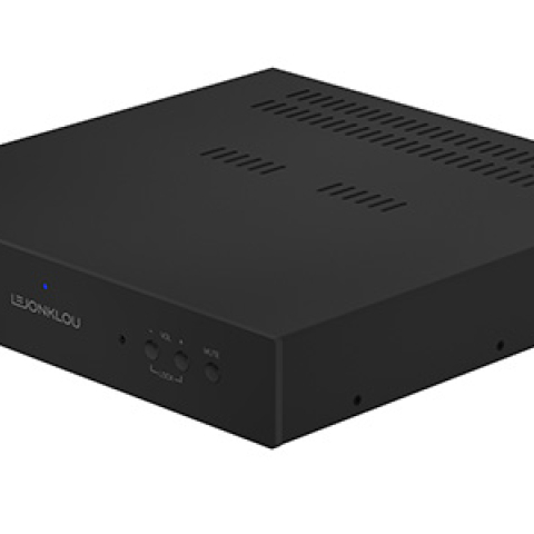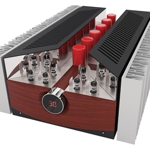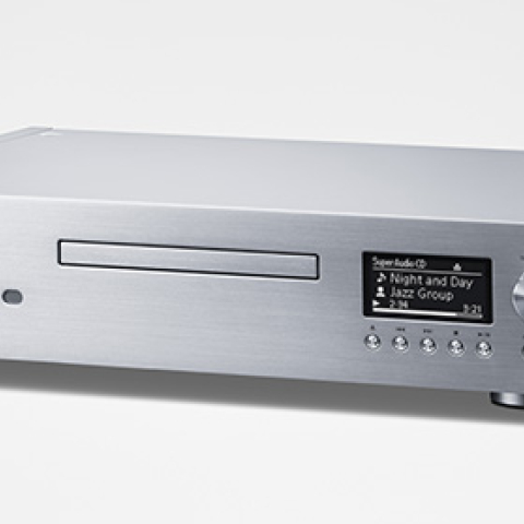
I examined the broken sample before returning it to Kora to be repaired. Michael's plugging in headphones, which the Explorer appears to drive from its power amplifier output, had blown the internal rail fuses. However, when I replaced these, they blew at the end of the tube warm-up period, suggesting that something had indeed broken in the power amplifier section. I performed all the measurements on the amplifier after it had been fixed. Unless stated otherwise, all the measurements were taken from the Explorer's speaker terminals, with the signal generator driving Input 1.
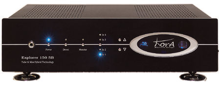
As is my usual practice, I preconditioned the Explorer 150SB by running it with both channels driven at ? power into 8 ohms for one hour, monitoring the level of distortion and noise in its output while I did so. This maximally stresses an amplifier's heat-dissipation abilities, and the Kora's chassis was very hot at the end of 60 minutes, with the top cover immediately above the internal heatsinks too hot to touch. The THD+noise level rose from 0.18% when cold to 0.24% after 15 minutes or so; it dropped back to 0.18% after another 15 minutes, then slowly rose again, to finish at 0.24%.
The maximum voltage gain into an 8 ohm load measured 39.5dB, which is typical for an integrated amplifier. What puzzled me, however, was that this was significantly less than the sum of the preamplifier and power amplifier gains, which I could measure individually, due to the Explorer's Direct operational mode allowing access to the preamp section outputs and power amp section inputs. The latter offered a modest 21.5dB of voltage gain into 8 ohms; the preamplifier section offered a maximum gain of 32dB. For the amplifier as a whole, the unity-gain setting of the volume control lay midway between the "–35" and "–40" markings on the dial. The Kora preserved absolute polarity—ie, was noninverting—via its main inputs, and its input impedance was a reasonably high 48k ohms in the midrange and below, dropping slightly and inconsequentially to 44k ohms at 20kHz. The output impedance from the Direct jacks was 2k ohms at 20Hz, dropping to a still high 1500 ohms in the midrange and treble.
The power amplifier output impedance was also on the high side for a solid-state design, ranging from 0.33 ohm at low frequencies to 0.45 ohm at the top of the audioband. The calculated figure also showed some dependence on the load impedance, suggesting that the Kora uses only a limited amount of loop negative feedback around its MOSFET-pair output stage. As a result, the modification of the amplifier's frequency response reached ±0.25dB when driving Stereophile's simulated speaker load (fig.1, top solid trace). Note the 1dB channel imbalance in this graph, which was taken with the Explorer's volume control set to "0"; the motorized control offered superb channel matching at the top of its range, but this got progressively worse in the region where it is most likely to be used. As the amplifier lacks a balance control, this behavior might be a problem when it comes to accurate soundstage reproduction.
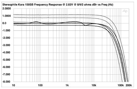
Fig.1 Kora Explorer 150SB, volume control = "0", frequency response at 2.83V into (from top to bottom at 2kHz): simulated loudspeaker load, 8 ohms, 4 ohms (1dB/vertical div., right channel dashed).
The Kora's small-signal bandwidth is impressively wide, this graph (fig.2) revealing a high-frequency –3dB point at 90kHz. However, the bandwidth depends on the volume-control setting; at full volume, the –3dB point moves up by almost an octave, to 149kHz, which results in superb reproduction of a 10kHz squarewave. Even so, I would have liked to have seen less interaction between the amplifier's bandwidth and the volume-control setting. Channel separation (measured at the speaker outputs with the undriven input short-circuited, not shown) was poor in the L–R direction, at 50dB at 1kHz, degrading to 27dB at 20kHz. It was somewhat better in the other direction, at 68dB at 1kHz and 56dB at 20kHz, but this is still disappointing performance.
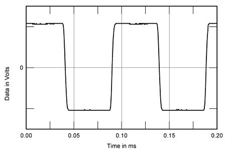
Fig.2 Kora Explorer 150SB, small-signal 10kHz squarewave into 8 ohms.
Fig.3 shows that the THD+N percentage present in the Explorer's output varied with output power, assessed into 8, 4, and 2 ohms. The downward slope of the traces below 30–40W in this graph reveals that the measured figure was dominated by noise, both of a random nature and of power-supply hum at 120Hz and 240Hz. (I tried all possible grounding arrangements between the Kora and my Audio Precision test set but couldn't eliminate the hum.)
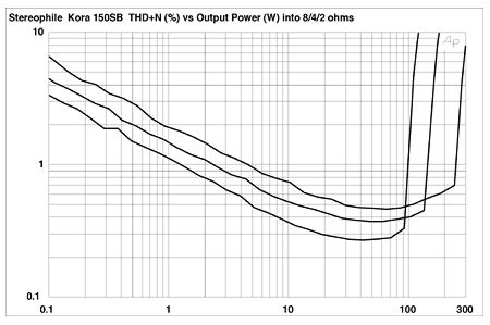
Fig.3 Kora Explorer 150SB, distortion (%)vs 1kHz continuous output power with (from bottom to top at 10W): two channels driven into 8 and 4 ohms, one channel driven into 2 ohms.
I was disappointed by the Explorer's noise levels: the A-weighted signal/noise ratio (ref. 1W into 8 ohms), measured at the speaker terminals with the volume control at its maximum and the input short-circuited, was a poor 50dB in the left channel, 58dB in the right. The unweighted wideband figures were even poorer, at 39dB left and 41dB right, due not only to the hum but to the presence of some low-frequency random noise. In actual use, the fact that the volume control will be set much lower than its maximum will drop the noise floor to more acceptable levels. However, the basic performance indicates that the amplifier has a less-than-optimal gain architecture, in my opinion.
Defining clipping as 1% THD, the Kora's output power with both channels driven was to specification, at 99W into 8 ohms (20dBW) and 150W into 4 ohms (18.75dBW). With one channel driven into 2 ohms, the Explorer delivered 250W at clipping (18dBW).
Even taking the power-supply noise into account, the Explorer offers quite high levels of distortion. Fig.4 plots the THD+N percentage against frequency at quite a high level, 11V, to ensure that the measurement shows distortion harmonics rather than noise. The level of distortion rises to alarming levels with both increasing frequency and decreasing load. Only into 8 ohm loads did the Explorer offer distortion levels that I would deem acceptable at this output level.
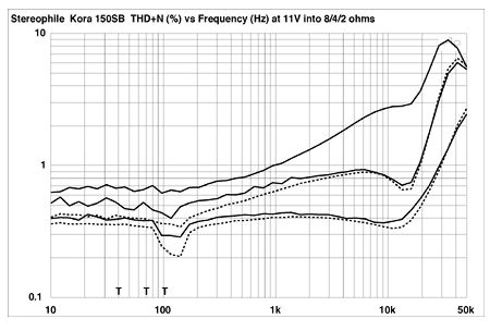
Fig.4 Kora Explorer 150SB, THD+N (%)vs frequency at 2.83V into (from bottom to top): 8 ohms, 4 ohms, 2 ohms (right channel dashed).
The absolute level of the distortion present in the Explorer's output will be ameliorated by the fact that the distortion is predominantly low-order in nature (fig.5), with the second harmonic highest in level at low frequencies (fig.6). However, the 120Hz and 240Hz power-supply components can be seen in this spectrum, as can the rise in the noise floor at low frequencies.
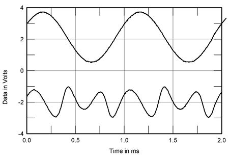
Fig.5 Kora Explorer 150SB, 1kHz waveform at 2W into 4 ohms (top), 0.3% THD+N; distortion and noise waveform with fundamental notched out (bottom, not to scale).
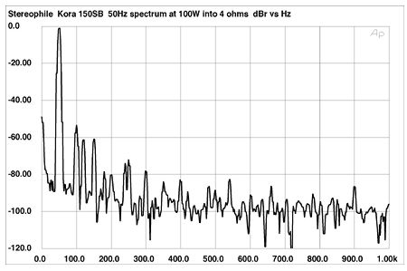
Fig.6 Kora Explorer 150SB, spectrum of 50Hz sinewave, DC–1kHz, at 100W into 4 ohms (linear frequency scale).
Despite the limited high-frequency linearity revealed in fig.4, the Explorer's behavior when fed an equal mix of 19kHz and 20kHz tones was quite respectable. The 1kHz difference component at a power level of 100W into 4 ohms lay at –63dB (0.07%), with the higher-order spuriae at or below this level (fig.7). Like the low-order nature of the harmonic distortion, this will tend to ameliorate the sonically degrading nature of the Explorer's relatively poor linearity.
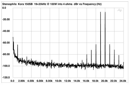
Fig.7 Kora Explorer 150SB, HF intermodulation spectrum, DC–24kHz, 19+20kHz at 100W peak into 4 ohms (linear frequency scale).
The Kora Explorer 150SB's measured behavior reveals it to be a marginal performer in a number of areas, in my opinion.—John Atkinson