Now to the Duo-Pivot design. Judy Spotheim explains that her design takes advantage of the fact that a so-called unipivot arm—ie, one without outrigger weight—will tip over to the arm's offset angle side. By adding a down-pointing tip on that side to act as a secondary pivot traveling laterally along an arc on a smooth platform close to the main pivot, very fine azimuth adjustments are made possible, even during play! Moreover, constant azimuth is maintained regardless of deviations from a perfect horizontal plane.
The Side-Thrust Bias Controller frees the arm from the tracking interference that Spotheim feels is inherent in most typical designs. Usually anti-skate devices are fixed at one end to the armwand, and to the arm's base at the other. "Regardless of whether they utilize a pulling spring, a spring pulling a string, a string pulled by a dangling weight, or a falling weight with a thread," she told me, "all such devices present a parasitic lateral mass tied to the armwand in front or behind the pivot. The anti-skate mechanism is thus activated not only by displacement in the arm's lateral plane, but also by displacement in its vertical plane, inhibiting the motion of the arm, especially when tracking records with any sort of warp. In contrast, the Side-Thrust Bias Controller doesn't present the arm and the pivot with an added lateral mass, nor does it tie or connect the armwand to any external fixed point. The result is it doesn't impair the tracking of the arm."
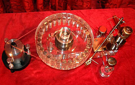
Pedestal
The arm is accompanied by a heavy stand-alone pedestal that supports the arm wires and the interconnect to the preamp. The pedestal stands to the rear of the 'table between platter and armboard. It's made up of a pair of slotted L-brackets bolted to a base. Between the brackets rides an acrylic board, adjustable for height and tilt and set with a knob on either side of the brackets. Stiff, unforgiving cables can be employed without disturbing the arm's lateral movement or rocking the boat—even if you use a floating suspension, as we did.
Incredibly, the pedestal also serves as a workstation for the arm when mounting the cartridge and setting Effective Length! For this purpose, clips attached to the side and top of the pedestal secure the arm in the horizontal and vertical planes. I have never played with a high-end device so completely thought through as the La Luce. What a pleasure.
Setup
The manual gives complete instructions for installing the platter and mounting the base plate, plus information on drilling "foreign" armboards for other 'tables. Small wooden wedges are provided for immobilizing the platter during these events. The SpJ arm lets you vary Effective Length by moving the cartridge along the headshell slots, by moving the arm's main pivot, and by twisting the cartridge to change the offset angle. These parameters can be set by using the overhang micrometer to move the main pivot relative to the spindle with the arm/cartridge already mounted. You twist the cartridge for the correct offset angle corresponding to the Effective Length you've set, regardless of the cartridge's location along the headshell slots.
The other way, as specified in the manual, breaks this procedure into two operations. The distance between the main pivot and the spindle is fixed during the arm-base installation (using the Baerwald overhang value as a reference), then the cartridge is aligned for an Effective Length of 244mm when first mounted. This distance is used for both Baerwald and Löfgren overhang values. Once the Baerwald overhang has been set, the switch to Löfgren (and back) can be done without moving the cartridge along the headshell slots. A high-quality metal alignment plate is provided, on which null radii points for both overhang values have been precisely inscribed. Spotheim reminds us that the hole on her gauge is precisely placed: cheap alignment gauges with misaligned spindle holes render their null points incorrect by definition.
Setting the pivot-to-spindle distance before the arm is in place need never be repeated, even when changing cartridges or switching overhang values—if that's your bag. Man. One sets the Baerwald value with a supplied metal gauge. A half-circle cut into one end of this snugs against the spindle; a cylinder with a hole drilled in it at the other end fits over the pivot tip. As instructed in the manual, I placed the gauge on the platter, shone a light at it from the other side, and squinted at the platter while raising VTA until the pivot lifted the flat bottom of the gauge off the platter. A quick turn in the opposite direction lowered VTA until the gauge lay perfectly flat. Catching the sliver of light underneath the gauge as it lifted off was a snap—the pivot tip was now in the same horizontal plane as that of the stylus tip resting on a record. This will also serve as the reference setting for VTA for most cartridges. (The van den Hul Grasshoppers are tall buggers and need greater height to achieve flat VTA.)
This is the time to calibrate the zero line of the VTA indicator plate by adjusting its micrometer and locking it in. Then one winds in the overhang micrometer until the half-moon cutout on the gauge is snug but not squashed against the spindle; lock it in place and remove the gauge.
Having clipped the tonearm to the pedestal, I moved my middle-aged corpus delecti over to a well-lit table and mounted the vdH Grasshopper IV GLA. I've been doing this for ages, but Judy Spotheim provides useful tips and the most complete hand-holding instructions on mounting cartridges you're ever likely to see. Once the 'Hopper was snugged in, I moved the arm to the vertical side clips on the pedestal to set overhang. I used the overhang tool—a tube as long as the arm, with a line inscribed around its circumference at one end and a fitting that mates with the arm's bearing at the other. Seating them together, one adjusts the cartridge so that its stylus "falls" into the inscribed line at the other end. Easy, ingenious, effective.
Then it was back to the 'table to apply the arm to its bearing on the horizontal platform, drop the pedestal in place behind the arm, and hook up the interconnect and ground wires. Then came the pushin' 'n' shovin' of both 'table and pedestal, until the whole contraption sat perfectly level (at the platter) on the Air Mass 2/Big Rock 1 support.
Having worked that out, there was still the offset angle to deal with, using the supplied metal template. Normally you'd sight on the body and parallel it with the lines inscribed on the offset-angle gauge. The 'Hopper has no body, of course; and, handmade beauty that it is, nothing lines up or is in any way orthogonal. Stylus pointing here, motor canted there...fawgedaboudit. Drives some people crazy.
But I don't mind. I lined up the 'Hopper on its stylus, with 1.43gm of VTF as measured by the ultra-ultra Winds Stylus Gauge. It took about five minutes of loosening the headshell screws and twisting the cartridge this way and that until I was satisfied the offset angle was right. Use of a low-power magnifier is much recommended for getting everything dialed in just so.
Most of you know me as a dental-floss guy. The Forsell uses a loop of The Dentist's Best Friend as a drive belt between its platter and the air-bearinged Flywheel. The La Luce, however, is designed with a stretchable drive belt. Spotheim: "I have chosen to decouple and isolate the motor from the platter without resorting to flywheels and additional belts. We have done so by designing the motor's pulley around these special and very fine flexible belts in combination with the various grooves on the motor pulley."
I was supplied with a plethora of belts. There was a white belt of 0.65mm cross-section with a stretch factor of 185%; a thin white belt, the Fine Bianca, with a 0.3mm cross-section and a stretch factor of 85%; and two versions of a delicate little number in blue and pink, known as Baby Thom or Pinky, with a 0.2mm cross-section and a stretch factor of 250%. Baby Thom needed careful handling and a push to start the platter, but sounded sweet and transparent. Spotheim: "The decision to use this frail-looking baby is based on its sonic merits. One Nordic audiophile wrote me that it's the closest you can get to driving the platter by sheer power of telepathy!"
I tried most of the belts, including the "rare" Violeta Special (200% stretch) and an unnamed black belt (180% stretch), but had good luck and best overall performance with the Fine Bianca. It maintained pitch stability and required very little attention. Leveling the stand-alone AC direct-drive synchronous motor and setting its height relative to the platter is easily accomplished via three locking knobs atop the motor-housing base. Fine-tuning the motor's speed relies not on electronics or frequency manipulation but on varying the belt tension by moving the motor closer or farther away from the platter. Moving the belt up or down the motor shaft's stepped circumferences made it easy to place the motor, and made simple the change-up to 45rpm.
The On/Off switch box carries a flexible 3m AC cord and connects to the motor with a standard IEC socket. You're advised to plug it into a circuit unburdened of household appliances, computers, neon lights, or dimmers. There are switches marked Power and Capacitor. For normal startup, one keeps Capacitor engaged so the 'table spins in the right direction. Once the platter is up and running, you can leave the Capacitor in-circuit, or take it out by snapping the toggle.
Spotheim: "We have chosen to include this special feature because of the enhanced purity of sound when the capacitor is omitted from the motor circuit." She recommends Capacitor-out operation for late-night and weekend listening. "We will, however, not be held responsible for any damage to cartridges or stylus assemblies caused by the platter turning counterclockwise!" You have been warned.
"The AC synchronous motor's pitch can be effected by small frequency shifts that occur simultaneously and in combination with odd-order harmonics of the AC line. This can cause temporary speed variations and unclean pitch. When voltage drifts low, for example, and the capacitor is not in the circuit, the platter can slow down. That's why it's a good habit to leave it in." And so I did, although I thought I detected, as suggested, a slight improvement late at night and on weekends with the Capacitor out of circuit.
The center of the platter is concave. Screwing down the small black knob on the acrylic disc clamp set over the LP's label area, with two rubber washers underneath the LP and around the spindle, made for excellent contact. When I tapped the vinyl, it was obvious how well this scheme worked at tightly coupling vinyl to platter—to remove some records, I actually had to pop the seal at the outside edge with my fingernail! Although the manual recommends stopping the platter before removing LPs, I found it more convenient to leave the 'table up and running during listening sessions. I'm used to changing records on a moving platter; the Forsell takes about two minutes to start and stop!
Azimuth, anti-skate, VTA
Evidently Judy Spotheim supplies a phase-switcher phono box to be used with a mono recording to set azimuth, but I didn't have that device from George Cardas, who knew I had the Audio-Technica Cartridge Analyzer (long out of production). Very convenient it was, azimuth perfectly set after only a short time spent raising and lowering the micrometer and checking the meter on the Analyzer. I used the Side-Thrust Bias Controller (STBC) to set anti-skating with the Cardas Sweep Record, which, in addition to degaussing your cartridge, has a blank band for testing anti-skating. Evidently Spotheim prefers her own anti-skate device, but alas (all together now), I didn't have that device from George—who knew I had a copy of his very useful record. Another two-minute job.
The manual contains a long and exhaustive examination of the close relationship of VTA and Effective Length: changing one alters the other. Spotheim points out that many contemporary cartridges attempt to incorporate a stylus rake angle (SRA) of 20°. But overall height (stylus tip to top plate) and cantilever compliance have never been standardized. And, taking a step or two back in the process, it's also widely known that the SRAs of various cutter-heads used over the years were themselves different from each other.
What to do? Spotheim suggests you forget the notion that a cartridge parallel to the record surface is at or near the sweet spot. Instead, she would have you adjust the VTA while listening, and note relative positions on the VTA indicator's scale. When you've dialed in VTA, check the scale's reading. Let's say it shows 1.25° of change down from the reference horizontal plane—one long line below the zero point. As she spells out in the manual, raising or lowering the pivot for VTA displaces the stylus tip from its overhang setting. Then she throws in this little pocket rocket: "This is true for both pivoted tonearms and linear-tracking types, the only difference being that with straight-tracking arms the stylus tip is displaced from its claimed true tangency, rendering moot the tangency concept central to such designs." Ahem.
"Certain audible improvements achieved by adjusting VTA without a compensating adjustment of overhang are actually nothing more than the manipulation of the stylus tip in the vicinity of a more accurate overhang setting. To properly adjust VTA away from the reference point, it is necessary to also adjust overhang to compensate for the displacement of the stylus tip caused by raising or lowering the arm." Damn, she doesn't split hairs, does she? But making the required adjustment is child's play on La Luce. To adjust for 1.25° of VTA change, one moves the arm's pivot 0.5mm forward by turning the overhang micrometer one full turn counterclockwise, and so on.


