
Plotting the small-signal THD+noise percentage against frequency (fig.4) indicated that the MD 208 was having to work hard both into low impedances and at high frequencies, presumably due to the relatively low level of loop negative feedback and limited open-loop gain-bandwidth product. Unusually, the level of distortion into our simulated loudspeaker load was higher at high frequencies, which might suggest some intolerance of loads with awkward electrical phase angles in this region. 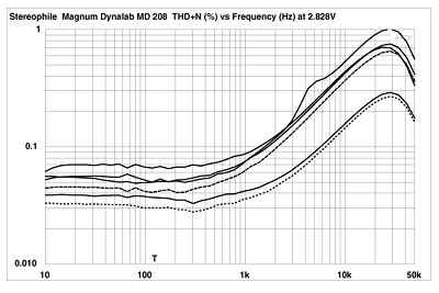 Fig.4 Magnum Dynalab MD 208, THD+noise (%) vs frequency at (from top to bottom at 4kHz): 2.83V into simulated loudspeaker load, 4W into 2 ohms, 2W into 4 ohms, and 1W into 8 ohms (right channel dashed). At moderate levels, the Magnum's distortion content was dominated by the second harmonic (fig.5), but at high powers (fig.6) the third harmonic became predominant. You can also see a full-wave rectified AC-supply component at 120Hz in this graph. The level of the 120Hz tone was unaffected by changes in the grounding scheme between the receiver and my Audio Precision System One test gear—and yes, while it is relatively low in level at about -78dB, it did increase with decreasing load impedance. Despite the reduced high-frequency linearity, intermodulation was acceptably low (fig.7). The punishing combination of 19kHz and 20kHz tones at an indicated 75W RMS into 4 ohms (just below visible clipping with this signal) produced a 1kHz difference component at -68dB (0.04%).
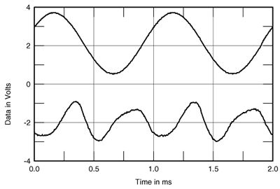 Fig.5 Magnum Dynalab MD 208, 1kHz waveform at 10W into 8 ohms (top), distortion and noise waveform with fundamental notched out (bottom, not to scale).
 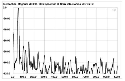 Fig.6 Magnum Dynalab MD 208, spectrum of 50Hz sinewave, DC-1kHz, at 125W into 4 ohms (linear frequency scale).
 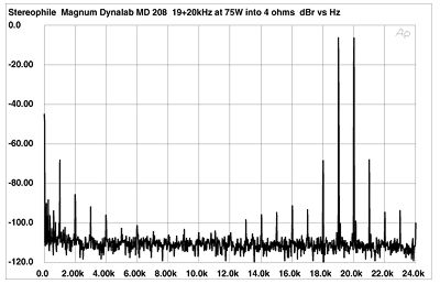 Fig.7 Magnum Dynalab MD 208, HF intermodulation spectrum, DC-24kHz, 19+20kHz at 75W into 4 ohms (linear frequency scale).
Fig.4 Magnum Dynalab MD 208, THD+noise (%) vs frequency at (from top to bottom at 4kHz): 2.83V into simulated loudspeaker load, 4W into 2 ohms, 2W into 4 ohms, and 1W into 8 ohms (right channel dashed). At moderate levels, the Magnum's distortion content was dominated by the second harmonic (fig.5), but at high powers (fig.6) the third harmonic became predominant. You can also see a full-wave rectified AC-supply component at 120Hz in this graph. The level of the 120Hz tone was unaffected by changes in the grounding scheme between the receiver and my Audio Precision System One test gear—and yes, while it is relatively low in level at about -78dB, it did increase with decreasing load impedance. Despite the reduced high-frequency linearity, intermodulation was acceptably low (fig.7). The punishing combination of 19kHz and 20kHz tones at an indicated 75W RMS into 4 ohms (just below visible clipping with this signal) produced a 1kHz difference component at -68dB (0.04%). Fig.5 Magnum Dynalab MD 208, 1kHz waveform at 10W into 8 ohms (top), distortion and noise waveform with fundamental notched out (bottom, not to scale). Fig.6 Magnum Dynalab MD 208, spectrum of 50Hz sinewave, DC-1kHz, at 125W into 4 ohms (linear frequency scale). Fig.7 Magnum Dynalab MD 208, HF intermodulation spectrum, DC-24kHz, 19+20kHz at 75W into 4 ohms (linear frequency scale).