Sidebar 3: Measurements
I used my Audio Precision SYS2722 to examine the Jadis JS1 MkV's performance. To minimize the possibility of the analog circuitry picking up noise from the power supply, I placed the supply on the floor, as far away from the processor chassis as the two umbilical cables would allow. The heatsinks on the back of the supply became very hot during testing, their temperature stabilizing at 135.3°F (57.4°C).
The processor's AES3 and optical and coaxial S/PDIF inputs locked to data sampled up to 192kHz. Apple's AudioMIDI utility revealed that the USB inputs accepted 32-bit integer data sampled at rates up to 768kHz. Apple's USB Prober utility identified the JS1 MkV as "Combo384 Amanero" from "Amanero Technologies\000," with the serial number string "414-001." (Amanero Technologies is an Italian company that manufactures USB and other OEM interface modules. The Combo384 USB module has been used in Stereophile-reviewed products from ATC, Métronome, and Verity.) The USB port operated in the optimal isochronous asynchronous mode.
Although the Jadis's maximum output level is specified as 2.5V RMS, a 1kHz digital signal at 0dBFS resulted in levels of 6.77V at the balanced output, 3.625V at the single-ended output. A look inside the JS1 MkV's chassis revealed that each channel of the analog circuitry has an ECC88 tube (footnote 1), followed by an ECC82 tube. As these tubes are both twin triodes, I assume that one-half of each tube handles the balanced signal's hot phase, the other the cold phase. The circuit contains no output transformers; the outputs of the ECC82s are capacitor-coupled to pins 2 and 3 of the XLR output jacks, and the single-ended outputs are connected in parallel with each XLR jack's pin 2.
The balanced output impedance varied from 2.4k ohms at 20Hz to 1.5k ohms at 20kHz. The single-ended output impedance varied in similar manner, from 1130 ohms to 619 ohms. Both outputs inverted absolute polarity, as can be seen from the impulse response with 44.1kHz data (fig.1). The output impedance is higher than I would expect from the usual cathode-follower circuit; that, together with the polarity inversion, suggests that the tube output stage might be based on an anode-follower topology, which some audiophiles feel sounds better.
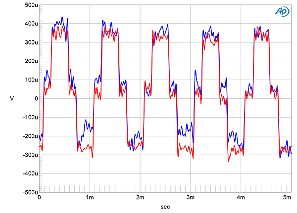
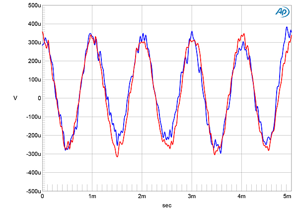
 When I examined the Jadis's output spectrum with a dithered 1kHz tone at –90dBFS with 16- and 24-bit data (fig.5), the increase in bit depth lowered the noisefloor above 3kHz by 12dB in the left channel and 15dB in the right. This suggests that the JS1 MkV offers between 18 and 19 bits' worth of resolution. However, the level of random noise is higher at lower frequencies, which reduces the resolution to around 17 bits in the midrange and to less in the bass. With undithered data representing a tone at exactly –90.31dBFS (fig.6), the three DC voltage levels described by the data were well resolved. However, a slight DC offset appears to be present in both channels. As this offset changes with time, I believe it is due to the presence of very low-frequency noise. As a result, with undithered 24-bit data (fig.7), the sinewave was slightly noisy.

Footnote 1: The review sample used the functionally identical 6922 tubes instead of ECC88s.
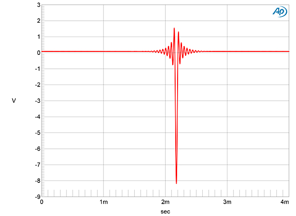
Fig.1 Jadis JS1 MkV, impulse response (one sample at 0dBFS, 44.1kHz sampling, 4ms time window).
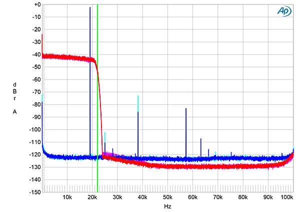
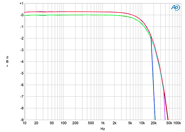
Fig.1 indicates that the JS1 MkV's reconstruction filter is a conventional linear-phase type, with time-symmetrical ringing on either side of the single sample at 0dBFS. With 44.1kHz-sampled white noise (fig.2, red and magenta traces), the reconstruction filter's response rolled off above 20kHz, reaching full stop-band suppression at 24kHz, just above half the sample rate (vertical green line). The aliased image at 25kHz of a 19.1kHz tone at 0dBFS (blue and cyan traces) is suppressed by more than 100dB, but the second and third harmonics of the 19.1kHz tone can be seen at –72dB and –82dB, respectively. The frequency response (fig.3) was flat up to 6kHz, with then a slow rolloff at all sampling frequencies that reached –2dB by 18kHz. The response then drops off sharply just below half of each sample rate. The right channel was 0.2dB higher in level than the left with both the balanced and unbalanced outputs.
Fig.2 Jadis JS1 MkV, wideband spectrum of white noise at –4dBFS (left channel red, right magenta) and 19.1kHz tone at 0dBFS (left blue, right cyan), with data sampled at 44.1kHz (20dB/vertical div.).
Fig.3 Jadis JS1 MkV, frequency response at –12dBFS into 100k ohms with data sampled at: 44.1kHz (left channel green, right blue), 96kHz (left channel cyan, right magenta), 192kHz (left gray, right red) (1dB/vertical div.).
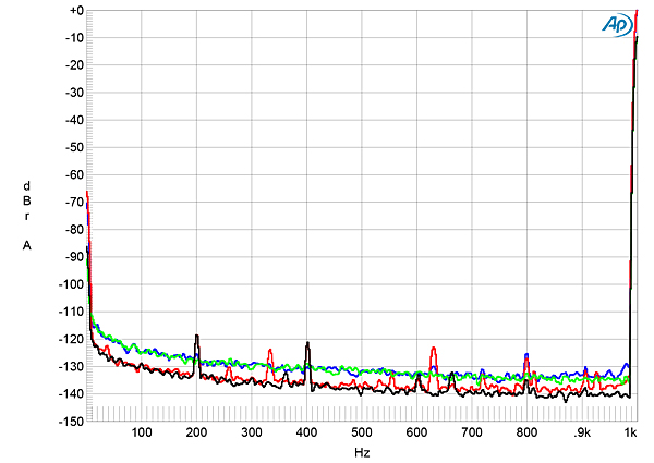
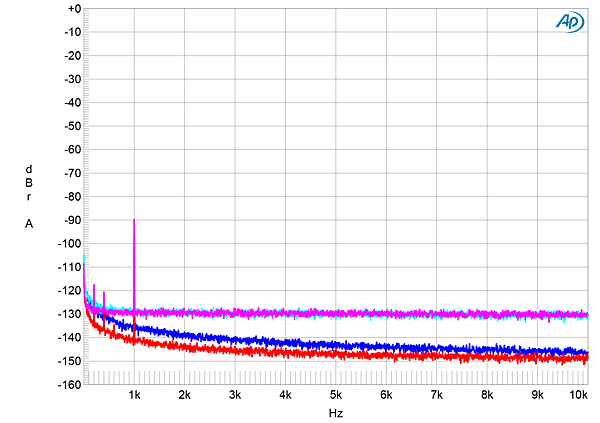
Channel separation was >110dB in both directions below 1kHz, falling to a still good 87dB at the top of the audioband. The JS1 MkV's random noisefloor was lower in the right channel (fig.4, red and gray traces) than the left (blue, green traces), with a rise at very low frequencies in both channels. This graph is free from power supply–related spuriae; low-level spuriae are present in the right channel at 200Hz, 400Hz, and 800Hz, none harmonically related to the signal frequency of 1kHz. When I reduced the signal level by 10dB (green and gray traces), these spuriae also dropped by around 10dB. Peculiar.
Fig.4 Jadis JS1 MkV, spectrum with noise and spuriae of dithered, 24-bit, 1kHz tone at 0dBFS (left channel blue, right red) and –10dBFS (left channel green, right gray) (20dB/vertical div.).
Fig.5 Jadis JS1 MkV, spectrum with noise and spuriae of dithered 1kHz tone at –90dBFS with: 16-bit data (left channel cyan, right magenta), 24-bit data (left blue, right red) (20dB/vertical div.).
Fig.6 Jadis JS1 MkV, waveform of undithered 1kHz sinewave at –90.31dBFS, 16-bit data (left channel blue, right red).
Fig.7 Jadis JS1 MkV, waveform of undithered 1kHz sinewave at –90.31dBFS, 24-bit data (left channel blue, right red).
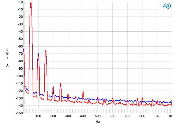
The JS1 MkV's distortion spectrum consisted primarily of the second and third harmonics (fig.8). Their levels were around –70dB (0.03%), which will be subjectively innocuous. The graph was taken into the high, 100k ohms load; the processor's output clipped when I reduced the load impedance to 600 ohms. The Jadis JS1 MkV needs to be used with preamplifiers that have an input impedance of at least 10k ohms. Intermodulation distortion with an equal-level mix of 19kHz and 20kHz tones and a high load impedance was relatively low (fig.9), with both the second-order product at 1kHz and the higher-order products at 18kHz and 21kHz lying at –80dB (0.01%).
Fig.8 Jadis JS1 MkV, spectrum of 50Hz sinewave, DC–1kHz, at 0dBFS into 100k ohms (left channel blue, right red; linear frequency scale).
Fig.9 Jadis JS1 MkV, HF intermodulation spectrum, DC–30kHz, 19+20kHz at 0dBFS peak into 100k ohms (left channel blue, right red; linear frequency scale).
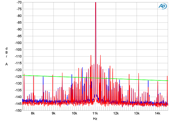
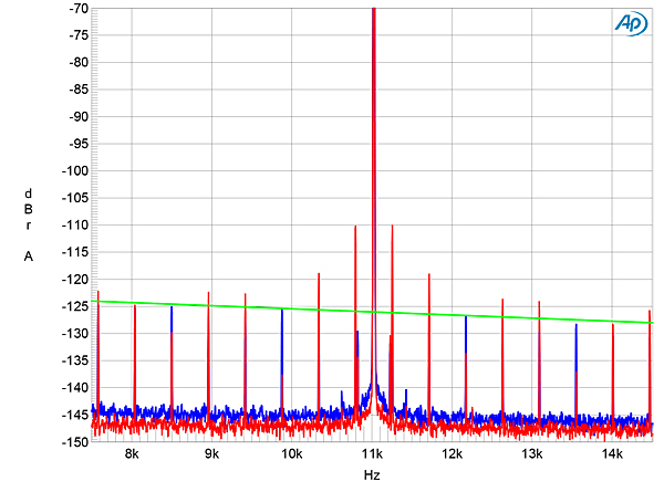
I tested the JS1 MkV for its rejection of word-clock jitter via its TosLink and AES3 inputs, using 16-bit J-Test data sampled at 44.1kHz. Some of the odd-order harmonics of the J-Test signal's LSB-level, low-frequency squarewave were close to the correct levels, shown by the sloping green line in fig.10, but others were either higher or lower in level. Also, a large number of sidebands are present. I initially assumed that these sidebands were power supply–related, but on examination they lie at ±85Hz and its multiples. When I repeated the test with USB data (fig.11), these sidebands were absent, which implies that they are due to idiosyncratic behavior of the Jadis's AES3 and S/PDIF receiver circuitry. And while most of the odd-order harmonics of the J-Test signal's low-frequency squarewave in fig.10 are now closer to the correct levels, those at ±229.6875Hz and ±459.375Hz are still too high. As the J-Test signal is not diagnostic with USB data, where the bit clock is not embedded in the data, the change in the levels of these sidebands has me at a loss regarding their cause. In any case, comparing figs.9 and 10 suggests that the Jadis processor will sound at its best using its USB input.
Fig.10 Jadis JS1 MkV, high-resolution jitter spectrum of analog output signal, 11.025kHz at –6dBFS, sampled at 44.1kHz with LSB toggled at 229Hz: 16-bit TosLink data (left channel blue, right red). Center frequency of trace, 11.025kHz; frequency range, ±3.5kHz.
Fig.11 Jadis JS1 MkV, high-resolution jitter spectrum of analog output signal, 11.025kHz at –6dBFS, sampled at 44.1kHz with LSB toggled at 229Hz: 16-bit USB data (left channel blue, right red). Center frequency of trace, 11.025kHz; frequency range, ±3.5kHz.
Other than the difference between the USB and the serial data inputs, the Jadis JS1 MkV's measured performance is dominated by the behavior of the tubed analog stage. To the presumably clean output of the AKM4497EQ DAC chip, it adds low-order harmonic distortion and a random noisefloor that increases in level at low frequencies. In other words: tube sound.—John Atkinson
Footnote 1: The review sample used the functionally identical 6922 tubes instead of ECC88s.


