Sidebar 3: Measurements
I measured the Parasound Halo Integrated using my Audio Precision SYS2722 system (see www.ap.com, and the January 2008 "As We See It"). As usual, I preconditioned the amplifier before measuring it by running both channels at one-third power into 8 ohms for an hour. At the end of that period, the top panel was hot, reaching 137.4°F (58.6°C) by the vents over the internal heatsinks.
I began by looking at the Halo's phono-stage performance, taking the amplifier's output from the fixed-level Rec Out jacks with the volume control at its minimum setting, so that the high-level tests wouldn't overload the power-amplifier stage. With the phono input set to moving magnet, the voltage gain was 34.2dB; set to moving coil, it was 53.8dB. Each value is appropriate for that type of phono cartridge. Measured at the speaker outputs with the volume control at its maximum setting, these phono-stage gains were 64 and 94dB, respectively. Both settings inverted absolute polarity. Set to 47k ohms, the input impedance was 47k ohms at 20Hz, 44.5k ohms at 1kHz, and 38k ohms at 20kHz; with this setting at 100 ohms, the input impedance measured 100 ohms at all audio frequencies.
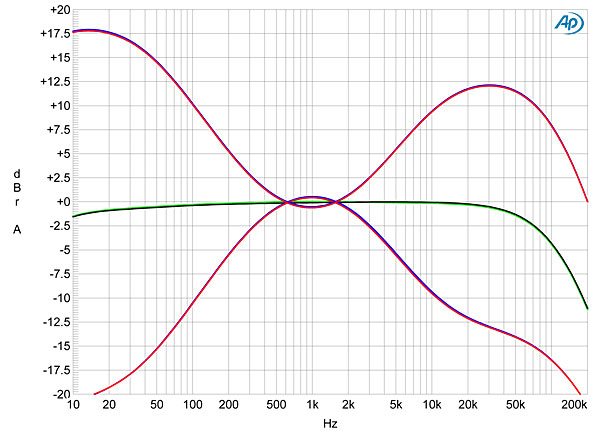
The RIAA response error was respectably low (fig.1), especially in the left channel (blue trace), but both channels can be seen to apply the so-called "Neumann fourth pole," resulting in an output that is up 9dB at 100kHz. While some justify this modification to the RIAA curve on theoretical grounds, I don't like to see it because it boosts the ultrasonic content of unequalized signals such as record ticks and clicks. Channel separation was high, at >70dB above 1kHz, and the signal/noise ratio, measured with the inputs shorted and a 22Hz–22kHz bandwidth, was good, at 69.8dB (MM, ref. 1kHz at 5mV) and 54dB (MC, ref. 1kHz at 500µV). A-weighting respectively increased these ratios to 69.9 and 61dB.


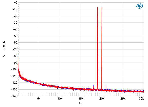


 Channel separation via the digital inputs was good, at >95dB in both directions below 7kHz. Feeding the Halo data representing a 1kHz tone with first 16-bit data (fig.8, cyan and magenta traces), then 24-bit data (blue, red), showed that the increase in bit depth dropped the noise floor by almost 20dB, which suggests that the Halo has better than 19-bit resolution. Repeating these measurements with USB data gave the same result, indicating that the Halo's USB input correctly handles 24-bit data. While many very low-level, power-supply–related spuriae can be seen in fig.8, these didn't affect the Halo's accurate reproduction of undithered 16-bit and 24-bit tones at exactly –90.31dBFS (figs.9 & 10).

 Channel separation at 1kHz was good rather than great, at 70dB, decreasing to 50dB at the top of the audioband. The wideband, unweighted S/N ratio, measured with the inputs shorted but the volume control at its maximum setting, was good, at 73dB ref. 2.83V into 8 ohms. This improved to 78dB when the measurement bandwidth was restricted to the audioband, and to 82.5dB when A-weighted. Spectral analysis revealed that AC supply components were at a low level (fig.16).
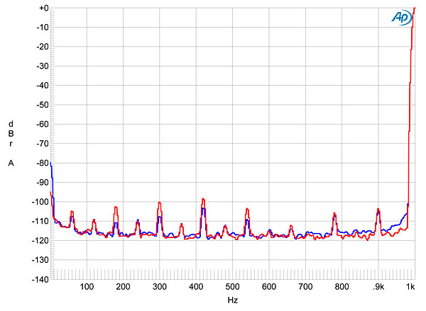

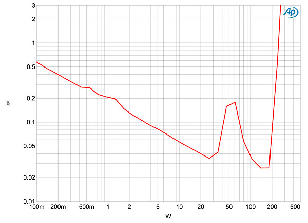


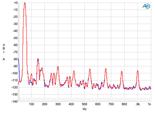

Fig.1 Parasound Halo Integrated, phono input, response with RIAA correction (left channel blue, right red) (1dB/vertical div.).
The Halo's phono stage was extremely linear. Even with a 1kHz signal at 20mV, the MM setting produced just a tiny amount of second-harmonic distortion (fig.2); and with an equal mix of 19 and 20kHz tones at the same equivalent level, there was a negligible amount of intermodulation distortion (fig.3). Correlating with this excellent linearity, the phono-stage overload margin was also excellent, at around 25dB across the audioband at both MM and MC settings.
Fig.2 Parasound Halo Integrated, phono input, spectrum of 1kHz sinewave, DC–10kHz, at 1V into 100k ohms (linear frequency scale).
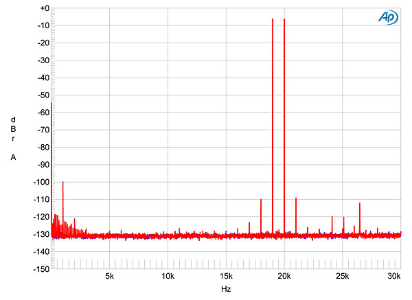
Fig.3 Parasound Halo Integrated, phono input, HF intermodulation spectrum, DC–30kHz, 19+20kHz at 1V peak into 100k ohms (linear frequency scale).
Turning to the digital inputs, again I assessed their performance at the fixed output jacks. Using my MacBook Pro on battery power to look at the USB input, this operated in the optimal isochronous asynchronous mode, and the Halo was identified as "PARASOUND—Digital Audio" with the manufacturer string "VIA Technologies Inc." The USB input accepted sample rates up to 384kHz, plus, unusually, 705.6kHz, and integer bit depths up to 32. The TosLink input accepted data with a 192kHz sample rate, which is commendable. All digital inputs preserved absolute polarity (ie, were non-inverting).
A full-scale tone at 1kHz resulted in an analog output of 1.92V at the fixed output. Because a tone at –20dBFS with the volume control at its maximum setting produced 18.7V at the speaker outputs, measured into 8 ohms, the digital inputs shouldn't be used with the volume control above 3:00 or so. The reconstruction filter's impulse response is shown in fig.3; the filter is a conventional, finite-impulse-response type with a response that rolls off rapidly above 21kHz with 44.1kHz-sampled data (fig.4, red and magenta traces). With a full-scale tone at 19.1kHz (blue, cyan), the third harmonic lies at –86dB (0.005%), suggesting that the digital circuitry offers low levels of harmonic distortion. This was confirmed by other tests (fig.6). Fig.7 shows the Halo's digital-input frequency response with sample rates of 44.1, 96, and 192kHz via the TosLink input, and 384kHz via the USB input. The ultrasonic output conforms to the same gentle rolloff, but rolls off sharply just below each Nyquist frequency (half the sample rate) at the three lower rates. At the 384kHz rate the smooth rolloff continues, reaching –18.5dB at 190kHz.
Fig.4 Parasound Halo Integrated, digital input, impulse response at 44.1kHz (4ms time window).
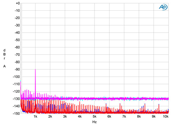
Fig.5 Parasound Halo Integrated, digital input, wideband spectrum of white noise at –4dBFS (left channel red, right magenta) and 19.1kHz tone at 0dBFS (left blue, right cyan), with data sampled at 44.1kHz (20dB/vertical div.).
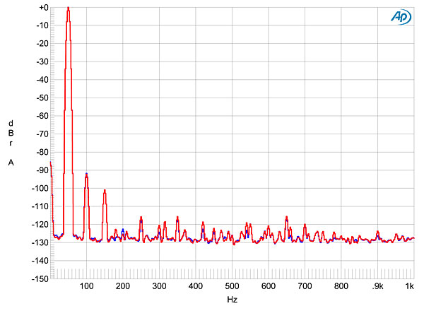
Fig.6 Parasound Halo Integrated, digital input, spectrum of 50Hz sinewave, DC–1kHz, at 0dBFS into 100k ohms (linear frequency scale).
Fig.7 Parasound Halo Integrated, digital input, frequency response at –12dBFS into 100k ohms with data sampled at: 44.1kHz (left channel green, right gray), 96kHz (left cyan, right magenta), 192kHz (left blue, right red), 384kHz (left gray, right, blue) (1dB/vertical div.).
Fig.8 Parasound Halo Integrated, digital input, spectrum with noise and spuriae of dithered 1kHz tone at –90dBFS with: 16-bit data (left channel cyan, right magenta), 24-bit data (left blue, right red) (20dB/vertical div.).
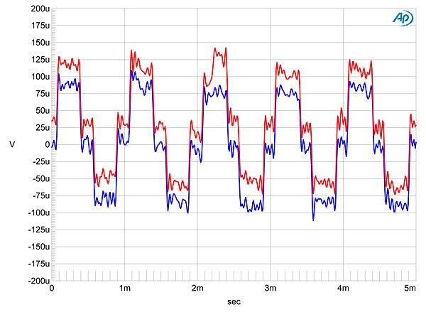
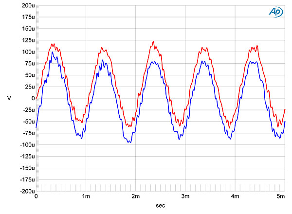
Fig.9 Parasound Halo Integrated, digital input, waveform of undithered 1kHz sinewave at –90.31dBFS, 16-bit data (left channel blue, right red).
Fig.10 Parasound Halo Integrated, digital input, waveform of undithered 1kHz sinewave at –90.31dBFS, 16-bit data (left channel blue, right red).
Intermodulation distortion via the digital input was negligible (fig.11), as were any jitter-related artifacts with both 16- and 24-bit J-Test data (fig.12).
Fig.11 Parasound Halo Integrated, HF intermodulation spectrum, DC–24kHz, 19+20kHz at 40W peak into 8 ohms (linear frequency scale).
Fig.12 Parasound Halo Integrated, digital input, high-resolution jitter spectrum of analog output signal, 11.025kHz at –6dBFS, sampled at 44.1kHz with LSB toggled at 229Hz: 24-bit data from SYS2722 via TosLink (left channel blue, right red). Center frequency of trace, 11.025kHz; frequency range, ±3.5kHz.
Turning to the Halo's behavior via its line inputs and measured at the speaker outputs, the maximum voltage gain at 1kHz was 39.6dB into 8 ohms via the balanced jacks, and 39.7dB via the unbalanced jacks. The balanced input impedance was 40k ohms across the audioband, and the unbalanced impedance was 24k ohms, again across the audioband. While the balanced input preserved absolute polarity, the unbalanced inputs were inverting.
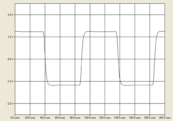
The output impedance was very low, at 0.09 ohm at 20Hz and 1kHz (including 6' of speaker cable), rising slightly to 0.11 ohm at 20kHz. The modification of the amplifier's frequency response by the interaction between this output impedance and that of our standard simulated loudspeaker was therefore very small (fig.13, gray trace). This graph indicates that the Halo has a wide bandwidth, the response into 8 ohms reaching –3dB at 100kHz. As a result, the Parasound's reproduction of a 10kHz squarewave was excellent (fig.14), with short risetimes and no overshoot or ringing. The traces in fig.13 were taken with the volume control at its maximum setting. Repeating the measurements at lower settings preserved both the close channel matching and the wide bandwidth.
Fig.13 Parasound Halo Integrated, volume control set to maximum, frequency response at 2.83V into: simulated loudspeaker load (gray), 8 ohms (left channel blue, right red), 4 ohms (left cyan, right magenta), 2 ohms (green) (2dB/vertical div.).
Fig.14 Parasound Halo Integrated, small-signal, 10kHz squarewave into 8 ohms.
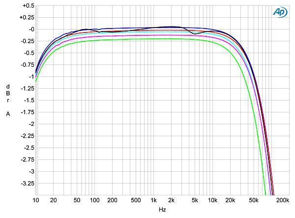
There was an audible 0.36dB insertion loss at 1kHz when the tone controls, set to their central, detented positions, were switched into circuit. Fig.15 shows the effect of the treble and bass controls set to their maximum and minimum settings; these are very similar in behavior to the controls of Parasound's Halo P 5 preamplifier, which Art Dudley reviewed in April 2014. The behavior of the Halo Integrated's subwoofer and crossover controls also look very similar to the P 5's.
Fig.15 Parasound Halo Integrated, frequency response at 2.83V into 8 ohms with tone controls set to: flat (left channel green, right gray), and maximum and minimum positions (left channel blue, right red).
Fig.16 Parasound Halo Integrated, spectrum of 1kHz sinewave, DC–10kHz, at 1V into 100k ohms (linear frequency scale).
Figs. 17 and 18 plot the percentage of THD+noise in the Halo's output as it drove 8 and 4 ohms, respectively. These graphs show that the Parasound met its specified power of 160Wpc into 8 ohms (22dBW) and 270Wpc into 4 ohms (21.2dBW) at 1% THD+N. Fig.19 plots the THD+N percentage against frequency at a fairly high level: 20V, equivalent to 50W into 8 ohms, 100W into 4 ohms, and 200W into 2 ohms. Fig.19 also shows that the amplifier offers low levels of distortion into the two higher impedances, but begins to stress out into 2 ohms. (The amplifier's protection circuit operated before the 2 ohm sweep was finished.) The distortion signature is strongly third-harmonic in nature (figs. 20 and 21), and intermodulation is also very low, even at high powers (fig.22).
Fig.17 Parasound Halo Integrated, distortion (%) vs 1kHz continuous output power into 8 ohms.
Fig.18 Parasound Halo Integrated, distortion (%) vs 1kHz continuous output power into 4 ohms.
Fig.19 Parasound Halo Integrated, THD+N (%) vs frequency at 20V into: 8 ohms (left channel blue, right red), 4 ohms (left cyan, right magenta).
Fig.20 Parasound Halo Integrated, 1kHz waveform at 50W into 8 ohms, 0.012% THD+N (top); distortion and noise waveform with fundamental notched out (bottom, not to scale).
Fig.21 Parasound Halo Integrated, spectrum of 50Hz sinewave, DC–1kHz, at 50W into 8 ohms (linear frequency scale).
Fig.22 Parasound Halo Integrated, HF intermodulation spectrum, DC–24kHz, 19+20kHz at 100W peak into 4 ohms (linear frequency scale).
The headphone output preserved absolute polarity, and was sourced from a 10 ohm impedance.
Like other Halo-series components from Parasound we have reviewed, the Integrated is a well-engineered, well-performing product.—John Atkinson


