Sidebar 4: Measurements
I measured the Line Magnetic LM-518IA using my Audio Precision SYS2722 system (see www.ap.com, and the January 2008 "As We See It"). Before starting the testing, I followed the instructions in the manual and left the amplifier turned on for 15 minutes; then, without any signal, I adjusted the bias of each 845 output tube to the correct value. (Very little adjustment was necessary.) Next, I short-circuited the inputs and, with the volume control at its maximum, adjusted the hum-balancer potentiometers to give the lowest measured noise for each channel. I performed a full set of measurements from each output-transformer tap.
The LM-518IA preserved absolute polarity from each output tap (ie, it was non-inverting), and its input impedance was very high, ranging from 59k ohms at 2kHz to 75k ohms at 20Hz. The maximum voltage gain, measured into 8 ohms, varied with the output tap, but was appropriate for an integrated amplifier: 40.2dB (16 ohm tap), 38.6dB (8 ohm tap), and 36.5dB (4 ohm tap). The output impedance varied slightly with frequency and load impedance, but was approximately one-quarter the nominal value of each output-transformer tap: 3.8 ohms (16 ohm tap), 2 ohms (8 ohm tap), and 1.1 ohms (4 ohm tap).
These impedances are relatively low for a single-ended-triode amplifier. As a result, the modification of the LM-518IA's frequency response due to the Ohm's law interaction between this impedance and that of our standard simulated loudspeaker remained within limits of ±0.8dB (4 ohm tap), ±1.2dB (8 ohm tap; fig.1, gray trace), and ±2.1dB (16 ohm tap). The traces in fig.1 were taken with the volume control set to its maximum—note the excellent channel matching, which was preserved at lower settings of the control. The frequency response into resistive loads is flat from 20Hz to 10kHz, with only a mild rolloff below 20Hz. The LM-518IA has an excellent output transformer. And though the secondary of this air-gapped transformer has a well-defined resonance at 60kHz, the associated response peak is low in level, particularly in the left channel, and that level doesn't rise with increases of load impedance.
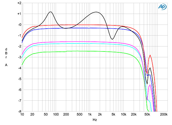
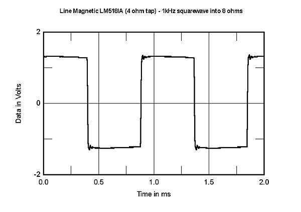
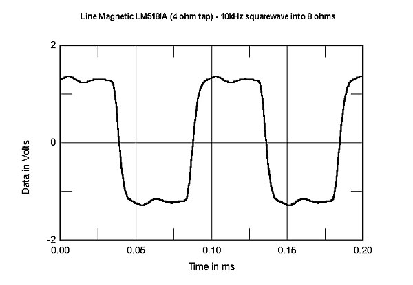
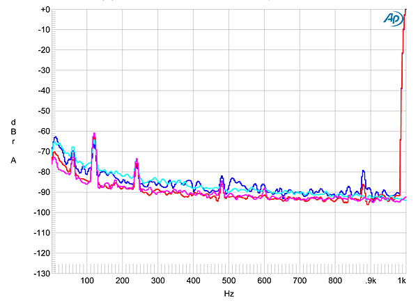

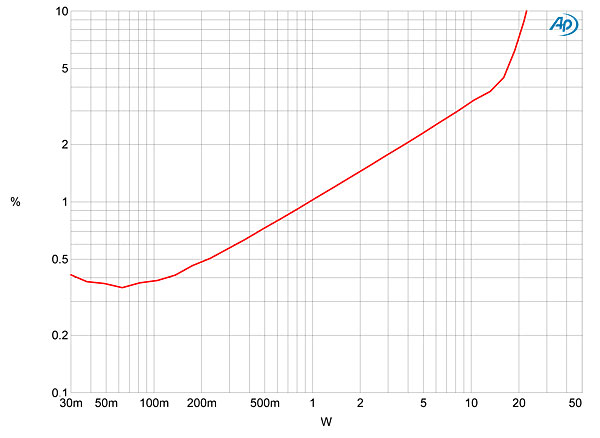

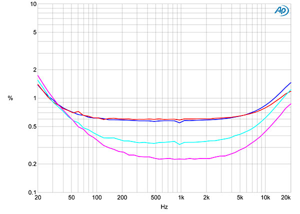


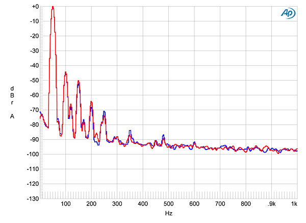
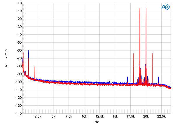
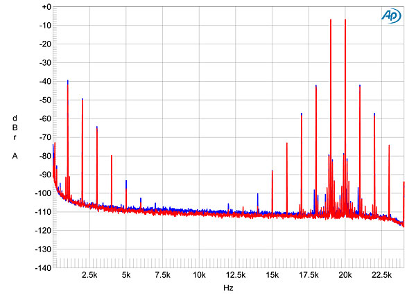
Fig.1 Line Magnetic LM-518IA (8 ohm tap), volume control set to maximum, frequency response at 2.83V into: simulated loudspeaker load (gray), 8 ohms (left channel blue, right red), 4 ohms (left cyan, right magenta), 2 ohms (green) (2dB/vertical div.).
Though a degree of overshoot can be seen in the LM-518IA's reproduction of a 1kHz squarewave (fig.2), the 10kHz squarewave (fig.3) reveals just one cycle of damped ringing. Note also the flat tops and bottoms of the waveform in fig.2, which correlate with the well-extended low frequencies seen in fig.1.
Fig.2 Line Magnetic LM-518IA (4 ohm tap), small-signal, 1kHz squarewave into 8 ohms.
Fig.3 Line Magnetic LM-518IA (4 ohm tap), small-signal, 10kHz squarewave into 8 ohms.
Even after the hum-balancer adjustment, the Line Magnetic's noise floor was higher than is typical for a tubed design. Measured with the inputs shorted but the volume control set to its maximum—the worst-case condition—the unweighted, wideband signal/noise ratios, ref. 2.83V into 8 ohms, were: 57.4dB (16 ohm tap), 59.7dB (8 ohm tap), and 61.5dB (4 ohm tap). Switching an A-weighting filter into circuit improved these ratios to, respectively, 65.6, 67.4, and 68.8dB, which will be barely adequate with high-sensitivity loudspeakers. Fig.4 indicates that while there are some power-supply–related spuriae, the highest in level being at 120Hz, this noise is predominantly random. The blue and red traces in fig.4 were taken with the LM-518IA driving 1W into 8 ohms with its volume control at the maximum setting; repeating the spectral analysis with the volume control at its minimum setting (fig.4, cyan and magenta traces) didn't lower the noise floor. This suggests that the noise occurs after the volume control, which means that, unlike other amplifiers, reducing the volume won't improve the S/N ratio. The channel separation at 2kHz was 80dB, L–R, but 60dB, R–L, these decreasing at 20kHz to, respectively, 58 and 40dB.
Fig.4 Line Magnetic LM-518IA (8 ohm tap), spectrum of 1kHz sinewave, DC–1kHz, at 1W into 8 ohms with volume control at: maximum (left channel blue, right red), minimum (left cyan, right red; linear frequency scale).
Figs. 5 and 6, both taken from the 4 ohm tap, respectively show how the THD+noise percentage changes with output power into 4 and 8 ohms. The LM-518IA is specified as offering a maximum power of 22Wpc (13.4dBW into 8 ohms, 10.4dBW into 4 ohms), and these graphs indicate that this power is achieved at just over 3% THD+N when the load impedance is the same as the nominal output-transformer tap. These graphs also indicate that, as usual with a SET design with minimal or no loop negative feedback, the THD+N increases linearly with output power above a couple of hundred milliwatts. Unusually, the LM-518IA is less linear when the load is higher than the nominal tap value (fig.6), and more linear when the load is lower than the nominal value (fig.7). The rather ragged appearance of the trace below 1W in fig.7 is due to the presence of very low-frequency "flicker noise."
Fig.5 Line Magnetic LM-518IA (4 ohm tap), distortion (%) vs 1kHz continuous output power into 4 ohms.
Fig.6 Line Magnetic LM-518IA (4 ohm tap), distortion (%) vs 1kHz continuous output power into 8 ohms.
Fig.7 Line Magnetic LM-518IA (16 ohm tap), distortion (%) vs 1kHz continuous output power into 8 ohms.
This can also be seen in fig.8, which plots the THD+N percentage from the 8 ohm tap at 2.83V into 8 and 4 ohms. The distortion was lower into 4 ohms (cyan and magenta traces) than into 8 ohms (blue, red). But, as expected from the LM-518IA's SET topology, the distortion is heavily second-harmonic (fig.9)—even at low frequencies (fig.10), when I would have expected some third harmonic to appear due to the onset of core saturation. Some third harmonic does appear when the load impedance is lower than the tap value, though it's still lower in level than the second harmonic (fig.11).
Fig.8 Line Magnetic LM-518IA (8 ohm tap), THD+N (%) vs frequency at 2.83V into: 8 ohms (left channel blue, right red), 4 ohms (left cyan, right magenta).
Fig.9 Line Magnetic LM-518IA, 1kHz waveform at 1W into 8 ohms, 0.58% THD+N (top); distortion and noise waveform with fundamental notched out (bottom, not to scale).
Fig.10 Line Magnetic LM-518IA (8 ohm tap), spectrum of 50Hz sinewave, DC–1kHz, at 1W into 8 ohms (left channel blue, right red; linear frequency scale).
Fig.11 Line Magnetic LM-518IA (8 ohm tap), spectrum of 50Hz sinewave, DC–1kHz, at 2W into 4 ohms (left channel blue, right red; linear frequency scale).
The LM-518IA's decreasing linearity at high frequencies (fig.8) will not be a problem when the load is the same as or less than the nominal value of the transformer tap. The second-order difference products at 1kHz (fig.12) lie at –60dB left and –70dB right (0.1% and 0.03%, respectively). But at higher powers, with a load impedance higher than the tap value, that product reaches 1% (fig.13).
Fig.12 Line Magnetic LM-518IA (8 ohm tap), HF intermodulation spectrum, DC–24kHz, 19+20kHz at 1W peak into 8 ohms (left channel blue, right red; linear frequency scale).
Fig.13 Line Magnetic LM-518IA (4 ohm tap), HF intermodulation spectrum, DC–24kHz, 19+20kHz at 5W peak into 8 ohms (left channel blue, right red; linear frequency scale).
I must admit, I was biased against the Line Magnetic amplifier before I began measuring it—its model number is similar to that of one of my least-favorite audio op-amp chips from my DIY days, National Semiconductors' LM318! But as I got deeper into the testing, the more impressed I became. Yes, as it's a single-ended-triode design, its bent transfer function leads to a nonlinear signature dominated by second-harmonic distortion. And it's noisier than I like to see. But for such a design, it offers high power. The only unusual aspect of its behavior is that, whereas I usually recommend that a tube amplifier be used with the lowest-value output-transformer tap that gives adequate loudness, the opposite is the case with the LM-518IA. Using its 16 ohm tap with 8 ohm speakers will give the lowest distortion, though the subjectively benign second harmonic will then be joined by some third harmonic.—John Atkinson


