John Atkinson measured the 500L, and I saw the results only after completing my auditioning. First, the 500L had a measured sensitivity of 86dB/W/m ("B"-weighted, measured with 20kHz-bandwidth noise). This is slightly higher than the specified 85dB figure, but within the margin of error. Fig.1 shows the 500L's impedance magnitude and phase angle, measured with our Audio Precision System One. The bass enclosure's bandpass tuning at 62Hz can be seen in the impedance minimum at that frequency. The minimum impedance is 1.98 ohms at 112Hz, but the speaker dips below 4 ohms between 80Hz and 600Hz. The 500L's nominal 5-ohm rating would seem appropriate, but the minimum specified impedance of 3 ohms is a little higher than the measured impedance. The somewhat low impedance, coupled with the less-than-benign phase angle in the same region, suggest that the 500L is a fairly demanding load for an amplifier. The VTL 225 monoblocks, however, had no trouble driving the 500L. (Incidentally, the tweeter's resonance can be seen as the tiny peak in the impedance curve at 26.4kHz.)
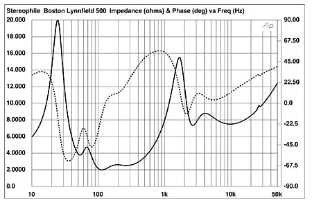
Fig.1 Boston Acoustics 500L, electrical impedance (solid) and phase (dashed) (2 ohms/vertical div.).
The measurements of the 500L's time and FFT-derived frequency-domain performance were taken with DRA Lab's MLSSA system, a calibrated B&K 4006 microphone, and an EAR mike preamplifier. The microphone's intrinsic on-axis response, measured in an anechoic chamber, has been subtracted from the measurement results to yield only the loudspeaker's behavior. Fig.2 is a composite of the 500L's midrange and tweeter anechoic responses, coupled with the nearfield output of the ports. The midrange unit is very smooth in its passband, but the tweeter appears to have a significantly elevated response between 5kHz and 10kHz. This no doubt contributes to my criticism of the speaker's treble.

Fig.2 Boston Acoustics 500L, acoustic crossover on tweeter axis at 50", corrected for microphone response, with nearfield midrange and bandpass woofer responses plotted below 300Hz.
Fig.2 also shows what appears to be a frequency mismatch between the tweeter's resonance and the AMD tuning: The tweeter ringing can be seen at 26.4kHz, and a very narrow notch, presumably due to the AMD, is apparent just below that frequency. The AMD appears to be mistuned, attenuating the band slightly below the tweeter's resonance rather than being positioned exactly at the tweeter resonance. Also in fig.2, we can see that the midrange driver's resonance modes, which appear as the two spikes at about 6kHz and 8kHz, are well down in level—about 30dB below the primary output. This suggests that the midrange AMD is very effective in suppressing narrow-band resonances.
According to Laurie Fincham's 1979 paper on bandpass woofer design (footnote 1), it is hard to eliminate high-Q resonances a few octaves above the unit's operating frequency. The 500L's woofer, for example, has a resonance that can be seen as the small spike at 600Hz. The speaker's bandpass output, centered on 60Hz, rolls off naturally at 12dB/octave. The woofer's low-pass crossover filter adds an additional 6dB/octave above 120Hz, resulting in an 18dB/octave acoustic low-pass function that helps suppress this resonance. (If the woofer is driven alone with pink noise, it can still be faintly heard as a "whistle.") Finally, the acoustic crossover points can be seen to be 90Hz and 2.1kHz.
JA modeled the crossover behavior from a schematic published in the Italian magazine AUDIOReview (footnote 2), producing the curves of fig.3. (The model necessarily assumes the drive-units are 8-ohm resistors.) The tweeter appears to be padded down by about 3dB, and has an extremely steep high-pass rolloff. This steep (approximately 60dB/octave) rolloff appears to be achieved by overlaying a fourth-order filter with a notch filter centered at 1320Hz. A slight downward slope can be seen in the midrange, perhaps to compensate for a rising drive-unit response on-axis. Both the low-pass and high-pass midrange rolloffs are 12dB/octave.
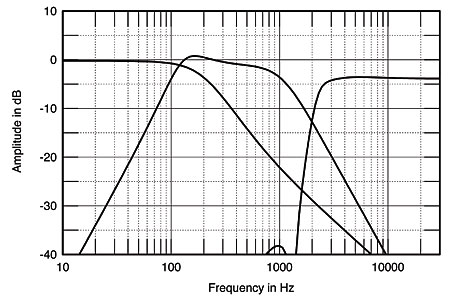
Fig.3 Boston Acoustics 500L, electrical response of crossover network, modeled with 98 ohms resistors replacing drive-units.
Fig.4 is the 500L's FFT-derived anechoic response averaged over a 30° lateral window on the tweeter axis and appended to the complex sum of the woofer ports' and the midrange unit's nearfield responses. Because of the ports' proximity to the floor, I expect the bandpass woofer's output to be higher than shown in the nearfield plot, resulting in excellent level-matching to the midrange's output. Indeed, my auditioning suggested that the upper-bass level was very well-balanced to that of the lower-midrange. The bass extension was only moderate, however, the woofer's quasi-anechoic –6dB point lying at 40Hz, though this will go a little lower in frequency in a typical room.

Fig.4 Boston Acoustics 500L, anechoic response on tweeter axis at 50", averaged across 30° horizontal window and corrected for microphone response, with complex sum of nearfield woofer and port responses plotted below 350Hz.
Note, however, the overall rising response with frequency in fig.4, and the plateau between 5kHz and 10kHz, correlating with my impression of a bright and forward mid-treble and lower treble. The top octave is more in line with the midrange level, but in comparison with the exaggerated region below, this probably ties in with my feeling of a slightly shut-in high-treble response. Again, the apparent AMD mistuning can be seen by the sharp dip just below the tweeter's resonance.
The 500L's vertical response family of curves is shown in fig.5. The plots represent the differences in response measured at different vertical positions, revealing just the changes in response to be expected at different listening heights. (As there is no difference between the reference response on the tweeter axis and itself, this appears in this graph as a straight line. Note that this does not mean the speaker has a perfectly flat response.) As would be expected from the 500L's high-order crossovers, there was very little change, particularly between the midrange driver and the top of the woofer cabinet—a typical listening-axis range. Note the large suckout (top two curves) at the crossover frequency if you sit too high. Overall, however, the sound won't change appreciably within the normal range of listening heights, as I found from my auditioning.

Fig.5 Boston Acoustics 500L, vertical response family at 50", normalized to response on tweeter axis, from back to front: differences in response 15°–5° above tweeter axis; reference response; differences in response 5°–15° below tweeter axis.
Fig.6 shows how the 500L's response changes as a function of lateral position to the inside edge (back) of the speaker's baffle (the edge nearest the drive-units) and the outside adege (front). Note how the presence region becomes more pronounced the farther off-axis on the drive-unit side. By contrast, the off-axis presence peak is much less severe on the other side of the baffle, suggesting that the midrange/tweeter enclosure should be positioned so that the drive-units are on the outside edge, not the inside edge as specified in the manual. In this position, however, absorptive material on the sidewalls (or better yet, ASC Studio Traps) will be essential if the sound is not to become too bright. Indeed, this was confirmed during the auditioning. The exaggerated presence-region off-axis suggests that the problems I heard in the auditioning will be exacerbated in rooms with reflective sidewalls. I had two ASC Studio Traps, positioned with their absorptive sides out, between the loudspeakers and the sidewalls. Although this would tend to mitigate the presence-region peak, I still heard too much treble energy.

Fig.6 Boston Acoustics 500L, horizontal response family at 50", normalized to response on tweeter axis, from back to front: differences in response 90°–5° off-axis on drive-unit side of baffle; reference response; differences in response 5°–90° off-axis on other side of baffle.
The treble rolloff off-axis suggests that the 500L's high-frequency balance may be more natural without toe-in. I found this to be the case when setting the speakers up, but I didn't get pinpoint image focus unless they were slightly toed-in. Note the very steep top-octave rolloff at more than 30° off-axis in fig.6, a phenomenon that may be due to interference from the tweeter's AMD.
Incidentally, JA visited my listening room to remeasure the new midrange/tweeter modules, which had been replaced after one of the original samples developed a buzz. Within the error due to the difficulty in positioning the microphone in three-dimensional space at precisely the same point, the two samples measured almost identically, suggesting excellent, tight production matching. We took the opportunity to measure the 500L's in-room response, averaged over five microphone positions near the listening seat (fig.7). The response looks very flat (footnote 3), but has more upper-midrange and treble energy than the same measurement performed on the much less bright Genesis III (see the III's in-room response in this issue's review). The bass lumpiness is a result of room modes rather than the loudspeaker's performance.
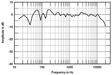
Fig.7 Boston Acoustics 500L, spatially averaged, 1/3-octave response in RH's room.
Turning to the time domain, fig.8 is the 500L's impulse response on the tweeter axis at 45". The hump after the impulse implies a high-order crossover. The ultrasonic tweeter ringing (the high-frequency stuff in the hump) is apparent, but is not severe. The bass unit's impulse response is shown in fig.9 while fig.10 shows the 500L's step response. Ideally, this should look something like a right triangle (see the Thiel CS3.6's step response in Vol.16 No.5, p.99, fig.4). The Lynnfield 500L's tweeter's output is the initial negative-going spike, implying inverted polarity, while the midrange output is the large positive-going hump, implying that the midrange unit is connected with the same positive polarity as the bandpass woofer.

Fig.8 Boston Acoustics 500L, impulse response on tweeter axis at 50" (5ms time window, 30kHz bandwidth).

Fig.9 Boston Acoustics 500L, nearfield impulse response of bandpass port (100ms time window, 1kHz bandwidth).
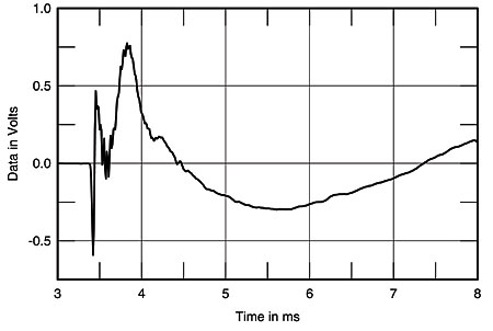
Fig.10 Boston Acoustics 500L, step response on tweeter axis at 50" (5ms time window, 30kHz bandwidth).
The 500L's cumulative spectral-decay, or "waterfall," plot is shown in fig.11. The decay is very clean and quick, but with a mild resonant mode noticeable at 2840Hz, revealed as the low-level vertical ridge at that frequency. As in fig.4, note the overall rising response with frequency.

Fig.11 Boston Acoustics 500L, cumulative spectral-decay plot at 50" (0.15ms risetime).
I drove the 500Ls with a sinewave oscillator to check for cabinet resonances. The ports produced significant wind noise at 85Hz at fairly high levels, while the woofer cabinet had some significant vibration accompanied by a change in tone at 130Hz. There was also a minor resonance noticeable at 480Hz. The satellite cabinet was relatively well-damped, there being only a few low-level modes noticeable between 250Hz and 550Hz. Fig.12 shows the waterfall plot calculated from a PVDF accelerometer's output when fastened to the satellite module's top panel. Note that, despite the rubber feet, a significant amount of vibration centered on the woofer's bandpass frequency makes its way through to the module.

Fig.12 Boston Acoustics 500L, cumulative spectral-decay plot of accelerometer output fastened to front baffle above tweeter (MLS driving voltage to speaker, 7.55V; measurement bandwidth, 2kHz).
Finally, I listened to the Listening Environment Diagnostic Recording (LEDR) from the first Chesky Test CD (JD37). The LEDR Test produced an excellent "lateral" image, with tight focus and no holes in the middle. The "up" test was moderately good, with the image moving above the loudspeaker, then stopping. The 500L also did well on the "over" test, with a continuous image arc produced over and between the loudspeakers.—Robert Harley
Footnote 1: "A Bandpass Loudspeaker Enclosure," presented at the 63rd AES Convention, 1979.—John Atkinson
Footnote 2: AUDIOReview, February 1993, p.122. The Italian reviewer also measured a rising response through the low- and mid-trebles.—John Atkinson
Footnote 3: It doesn't surprise me that a flat measured in-room response at the listening position sounds bright. Loudspeaker- and room-correction devices that equalize a system for flat response at the listening seat always make the sound too bright, at least to judge from the demonstrations I've heard.—Robert Harley