I examined the Balanced Audio Technology REX 500's measured behavior with my Audio Precision SYS2722 system. Before I started the testing, I made sure that the four Reset buttons, two for each channel, were pushed in, as advised in the manual. I preconditioned the REX 500 by following the CEA's recommendation of running it at one-eighth the maximum power into 8 ohms for 30 minutes. At the end of that time, the temperature of the top panel was 99.9°F (37.8°C) and that of the heatsinks 134.0°F (56.7°C). The REX 500 has sufficient heatsink capacity for its high output power. The amplifier also ran hot during the testing, which suggests the output stage is heavily biased into partial class-A operation.
I performed all the testing using the BAT's balanced inputs, then examined the gain, polarity, and input impedance of the single-ended inputs using a Cardas RCA-XLR adapter. Both input types preserved absolute polarity, ie, were noninverting. BAT specifies the REX 500's input impedance as 215k ohms; I measured a lower but still very high 180k ohms at 20Hz, 172k ohms at 1kHz, and 66k ohms at 20kHz for the balanced inputs. The single-ended input impedance was just above half those figures, which is still usefully high. The voltage gain was 26.67dB for the balanced inputs, 26.55dB for the single-ended inputs.
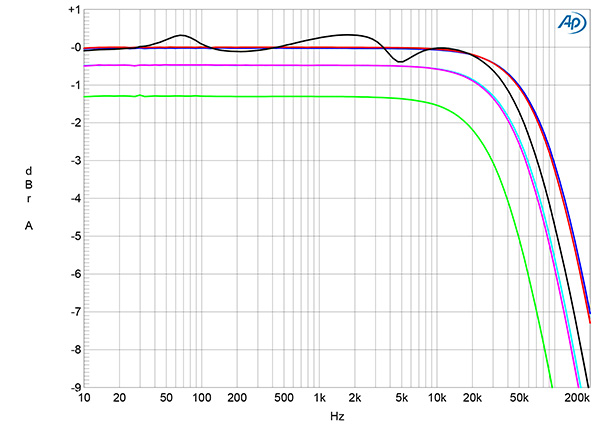
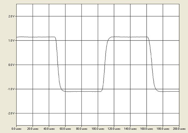
The REX 500 amplifier's output impedance, including the series impedance of 6' of spaced-pair cable, was relatively high, at 0.45 ohms at low and middle frequencies and 0.6 ohms at the top of the audioband. As a result, the variation in the frequency response with our standard simulated loudspeaker (fig.1, gray trace) was ±0.3dB. The response into 8 ohms (blue and red traces) was flat in the audioband, then started to roll off above 20kHz. The high-frequency rolloff started lower in frequency into 4 ohms (cyan and magenta traces) and into 2 ohms (green trace), where the output was down by 0.8dB at 20kHz. The response into 8 ohms reached –3dB at 95kHz; this wide small-signal bandwidth correlated with short risetimes in the BAT's reproduction of a 10kHz squarewave into that load (fig.2). Commendably, the waveform didn't have any overshoot or ringing.
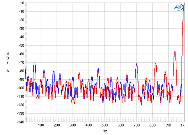
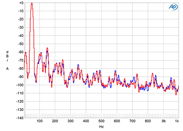
As expected from the dual-mono topology, channel separation was superb, at >100dB below 2kHz in both directions. The unweighted, wideband signal/noise ratio, taken with the balanced input shorted to ground, was a good 69dB (average of both channels) ref. 1W into 8 ohms. The right channel's ratio improved to an excellent 85.0dB when the measurement bandwidth was restricted to 22Hz–22kHz but in the left channel was only marginally improved, at 69.5dB. Switching an A-weighting filter into circuit improved the right channel's ratio to 92.3dB, the left channel's to 81.9dB. Spectral analysis of the low-frequency noisefloor while the BAT drove a 1kHz tone at 1Wpc into 8 ohms (fig.3) revealed that the lower S/N ratio in the left channel was due to a higher level of the supply-related spurious tone at 60Hz (blue trace). The random noisefloor is higher than I would have expected, and there are sidebands at ±60Hz present in both channels around the spectral spike that represents the 1kHz tone. This behavior will be due to magnetic interference from the massive power transformers.
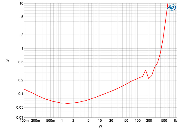
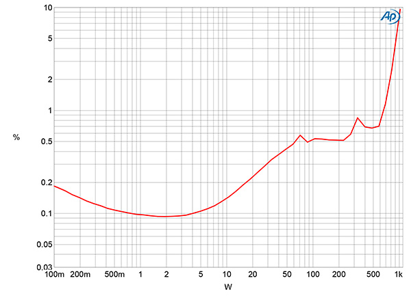
BAT specifies the REX 500's maximum continuous power as 500W into 8 ohms and 1000W into 4 ohms, both equivalent to 27.0dBW. With the clipping power defined as when the THD+noise reaches 1%, with both channels continuously driven with a 1kHz tone the REX 500 clipped at 416W into 8 ohms (26.2dBW, fig.4) and 680W into 4 ohms (25.3dBW). At 3% distortion, the amplifier exceeded its specified power into 8 ohms, clipping at 520W (27.16dBW). It clipped at 850W into 4 ohms (26.28dBW) at 3% THD+N; the AC wall voltage had dropped from 118.4V with the amplifier idling to 113.1V at this power. The distortion is relatively low below 10W in these two graphs but steadily rises as the power increases, presumably due to the absence of global loop negative feedback. When I examined the maximum continuous power into 2 ohms with one channel driven, the amplifier clipped at 800W (23dBW, not shown), but the distortion exceeded 1% at powers above 68W.
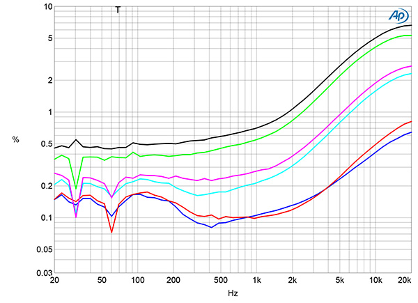
The THD+N percentage at 12.67V, equivalent to 20W into 8 ohms, 40W into 4 ohms, and 80W into 2 ohms, was relatively low below 1kHz into 8 ohms (fig.6, blue and red traces) and as expected from figs.4 and 5, was higher into 4 ohms (cyan, magenta traces) and 2 ohms (green, gray traces). However, the THD+N rose significantly in the top audio octaves into all loads, which implies that the REX 500 has a limited open-loop bandwidth. The distortion at this voltage into 2 ohms was >3% at frequencies above 6kHz.
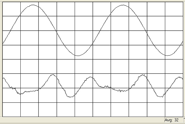
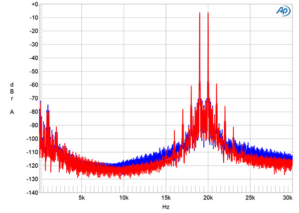
The distortion waveform into 8 ohms was predominantly the second harmonic (fig.7), though the third harmonic was highest into 4 ohms (fig.8). Commendably, there are no crossover distortion spikes visible in this graph, which confirms the high output-stage bias. With the circuit's reduced linearity at high frequencies seen in fig.6, the REX 500 didn't do well when handling an equal mix of 19 and 20kHz tones at a peak level of 50W into 8 ohms (fig.9). While the second-order difference product lay at an okay –76dB (0.015%), the higher-order intermodulation products at 18kHz and 21kHz were higher in level, at –60dB (0.1%). A plethora of supply-related products is visible in this graph. The high-order products rose to –50dB (0.3%) at the same peak voltage into 4 ohms (not shown).
The Balanced Audio Technology REX 500's performance on the test bench indicates that it offers high powers but with higher-than-usual levels of both harmonic and intermodulation distortion. In this respect, it resembles a tubed amplifier, which might be expected from a company known for its tubed designs. That the relatively innocuous second and third harmonics predominate in the distortion signature is a note in its favor.—John Atkinson