| Columns Retired Columns & Blogs |
Cut and Thrust: RIAA LP Equalization
Until the Recording Industry Association of America hit the headlines in recent years with its antipiracy campaign, the initials RIAA meant one thing to seasoned audiophiles: the vinyl-disc equalization characteristic introduced in the 1950s to standardize what had previously been an anarchy of different EQs. Three decades later, as CD gained ascendance, a large proportion of audiophiles still knew what RIAA equalization was, and a good number of them had some idea or better of what the RIAA EQ curve looked like, and why it was applied.
Footnote 1: There have been hi-fi pickup cartridges that are displacement transducers, generating an output voltage proportional to stylus displacement rather than velocity, but they are rarities. The Decca Deram ceramic cartridge was one popular example. Such cartridges—which have mostly occupied the cheaper end of the market and used either piezoelectric ("crystal") or electrostrictive ("ceramic") generators—require different, milder replay equalization to account for the differences between the RIAA record characteristic and a true constant amplitude cut. This is usually achieved internally, allowing them to be connected to a "flat" preamp input.

But that was a generation ago. In the interim, vinyl replay has dwindled to a small if still thriving niche of the hi-fi industry, and a new flush of audiophiles exists to whom the subject of disc equalization may be unknown or, at the very least, arcane. Yet the subject occasionally reemerges, such as in the recent debate about the "Neumann ultrasonic time constant." If the history of and theory behind RIAA/IEC (International Electrotechnical Commission) disc equalization are mysteries to you—or have faded from memory—then this article will bring you up to speed and up to date. Everything the audiophile (though not the design engineer) really needs to know about the subject is here.
The requirement for disc equalization exists because of the nature of the cutting head used to gouge the groove into the lacquer master disc, and that of the pickup cartridge used to replay the pressed vinyl record. Both are normally velocity transducers, the significance of which will shortly become apparent.
First, let's consider the nature of the modulations (wiggles, if you like) that we wish to impose on a record groove. Ideally, we would want them to be constant-amplitude in nature, so that a given signal level at, say, 100Hz occupies no more or less lateral space than the same at 10kHz. (I'm thinking of a mono record here, or a stereo one in which the signal is at equal amplitude and in phase in both channels, so as to produce purely lateral movement of the cutting stylus.) This will prevent any part of the audible spectrum from hogging too much disc space, and ensure that the groove modulations are, so far as possible, large relative to the asperities of the groove surface, thereby maintaining a good ratio of signal to noise.
In order to cut a record groove with a constant-amplitude characteristic, it is not sufficient to provide a signal of flat frequency response to the cutting head because the latter is electromagnetic by operation, and hence, as already mentioned, a velocity transducer. It generates at the cutting stylus a velocity, not a displacement, proportional to the input voltage.
Fig.1 illustrates the consequences of this by showing two in-phase sinewaves, one twice the frequency of the other. Because the peak velocity of a sinewave—which occurs at the zero crossing point—is proportional to both amplitude and frequency, the amplitude of the higher-frequency sinewave must be half that of the lower-frequency wave in order for them to have equal velocity. It follows that if we feed the cutting head with a signal having a flat frequency response, high-frequency components will be cut into the groove at lower amplitude than low-frequency components.
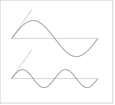
Fig.1 Two sinewaves, one twice the frequency of the other. For their peak velocities (red lines) to be equal, as shown here, the higher-frequency wave must be of half the amplitude. This is what would happen if a flat-response signal were fed to a record cutter: the amplitude of the groove modulation would halve for each doubling of frequency. To prevent this, preemphasis is applied.
To obviate this and produce the constant-amplitude cut we desire, electronic equalization (called preemphasis) must be applied to the signal fed to the cutter. Ideally, this preemphasis needs to double the signal voltage for every doubling of frequency, equivalent to a 6dB/octave rise throughout the audible frequency range. This is illustrated as the red line in fig.2 alongside the actual RIAA preemphasis curve (blue), which doesn't deliver an exact constant-amplitude cut but a fair approximation of it. (The reason for not adopting a true constant-amplitude correction is that it would require 60dB of amplification at 20kHz relative to 20Hz, equivalent to 1000x gain, whereas the kinked RIAA curve requires only about 40dB of amplification, equivalent to 100x gain.)
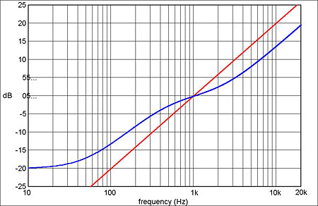
Fig.2 RIAA preemphasis (record) curve (blue), with the +6dB/octave equalization required for a true constant-amplitude cut (red).
Because the pickup cartridges used to replay records are usually electromagnetic transducers as well, they act like the cutter in reverse, generating an output voltage proportional to the velocity of the groove modulation. So to restore a flat frequency response, replay equalization (deemphasis) that is the inverse of the record equalization must be applied. This is done in the disc input stages of the replay system's preamplifier (footnote 1).
The RIAA pre- and deemphasis curves are defined by three time constants (T), each of which is related to a corner frequency (f) in the amplitude response by the equation:
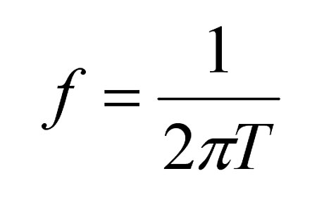
These time constants (3180, 318, and 75 microseconds) and their respective corner frequencies (50.05, 500.5, and 2,122Hz) are depicted in the red trace of fig.3, which shows the straight-line approximation of the RIAA deemphasis (ie, replay) curve, alongside the actual curve (blue). Note that the latter is a mirror image of the preemphasis curve in fig.2, so that the two are exactly complementary: applying the deemphasis on replay cancels the effect of the preemphasis applied during cutting, to leave a flat response overall (footnote 2).
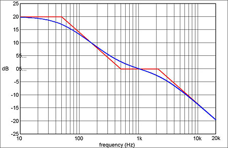
Fig.3 RIAA deemphasis (replay) curve (blue), which is the inverse of the preemphasis curve in fig.2. Red trace shows the straight-line approximation based on the filter's time constants.
Although originating in the US, RIAA record and replay equalization were quickly adopted internationally, and duly became part of the IEC 98 standard, first published in 1964 (now, in revised form, IEC 60098, "Analogue Audio Disk Records and Reproducing Equipment"), which described a lot more besides concerning the format and dimensions of microgroove records.
All was hunky-dory until September 1976, when, in its inscrutable Swiss way, the IEC thrust an unexpected wrench in the works with an Amendment to IEC 98 that included a change to the replay characteristic. A fourth time constant was added (7950µs, corresponding to 20.02Hz) that imposed a 6dB/octave rolloff at frequencies below audibility, the intention being to reduce the levels of infrasonic frequencies generated by record warps and ripples and the fundamental arm-cartridge resonance being passed along to the amplifier and, particularly, the loudspeakers (footnote 3).
Howls of protest greeted this development, for reasons both philosophical and practical. Objectors railed against the lunacy of unpicking the complementarity of the record and replay equalizations (the preemphasis applied at the recording end remained unchanged), and pointed out that if excess infrasonic output was sometimes a problem with vinyl disc replay, then it would be more logical to tackle it on a switchable basis by using sharper high-pass filtering.
The force of the latter objection is clear from fig.4, which compares the original RIAA/IEC replay characteristic (blue trace) with the IEC revision (orange), and graphs the difference between them from 1 to 100Hz. Because it generates a slow, first-order rolloff, the extra replay time constant introduces significant response errors within the audible range (–3.0dB at 20Hz, –1.0dB at 40Hz, –0.5dB at 60Hz), and is quite poor at suppressing the frequencies of concern. Attenuation at 13Hz (a good frequency to place the arm-cartridge fundamental resonance) is just 5.3dB, or 0.54x; and, at 4Hz (a typical record-ripple frequency), 14.2dB, or 0.20x.
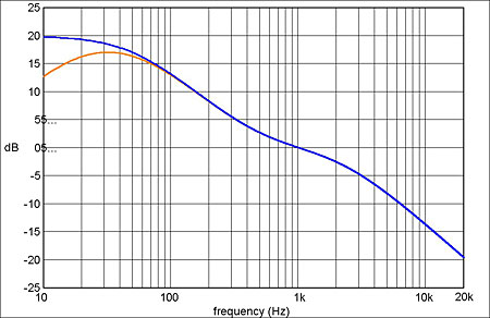
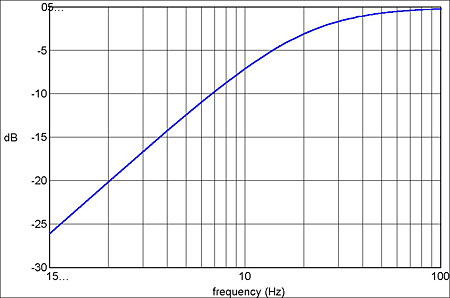
Fig.4 a) Repeat of the RIAA deemphasis curve, the orange curve showing the effect of the additional IEC time constant; and b) the difference introduced by the latter up to 100Hz.
Footnote 1: There have been hi-fi pickup cartridges that are displacement transducers, generating an output voltage proportional to stylus displacement rather than velocity, but they are rarities. The Decca Deram ceramic cartridge was one popular example. Such cartridges—which have mostly occupied the cheaper end of the market and used either piezoelectric ("crystal") or electrostrictive ("ceramic") generators—require different, milder replay equalization to account for the differences between the RIAA record characteristic and a true constant amplitude cut. This is usually achieved internally, allowing them to be connected to a "flat" preamp input.
Footnote 2: It is worth noting here that diagrams of the RIAA curves that show the ±3dB points either side of 1kHz to coincide with the 318 and 75µs time constants—for example, fig.12.3 in the Audio Electronics Reference Book, edited by Ian Robertson Sinclair (Blackwell Science, 1989)—are incorrect. To be accurate, the responses are actually ±2.73dB at 500.5Hz and ±2.78dB at 2122Hz for the record and replay curves, respectively, with the response at 1kHz being ±0.09dB. (This using the equations given in IEC 60098.) If the responses are normalized to 0dB at 1kHz, then the figures become ±2.64dB at 500.5Hz and ±2.87dB at 2122Hz.
Footnote 3: In this era of digital audio sources, it is easy to forget what a problem this could be, particularly with reflex-loaded loudspeakers whose bass cones would sometimes undergo large excursions, driving the reproduction of audible frequencies into premature nonlinearity. The current hegemony of reflex-loaded speakers and the relative rarity of closed-box designs was initiated by the arrival of CD.
- Log in or register to post comments

