During an Audio Engineering Society meeting where a former colleague of mine was giving an arcane technical discussion of the optical considerations of data retrieval from a Compact Disc, a longtime AES member whispered to me: "What happened to the good old days of AES meetings when we talked about things like tape bias and saturation?"
 Although I found this quite funny, his reaction exemplifies the quandary of trying to keep pace with the rapidly changing technology of the late 20th century. As the field of audio recording and reproduction becomes more and more sophisticated, we are forced to learn new terminology, new concepts, and, significantly, a new lexicon as we make the transition from analog to digital technology. Where we once discussed VTA, wow and flutter, and compliance, a contemporary audio conversation is more likely to include such terms as EPROMs, jitter, MIPS, and DSP. Today's audio jargon reflects the huge impact computer technology has had on audio equipment.
This revolutionary change really hit home as I was writing the technical description of the Wadia X-32 Digital Decoding Computer. The X-32's technical features throw into sharp relief the changing times. I found myself describing programmable gate arrays, Erasable Programmable Read-Only Memory chips, updateable architecture, Digital Signal Processing chips, clock signals, and jitter reduction circuits.
So hang onto your hats as we rush headlong into the brave new world of digital playback.
Technical description
Although I found this quite funny, his reaction exemplifies the quandary of trying to keep pace with the rapidly changing technology of the late 20th century. As the field of audio recording and reproduction becomes more and more sophisticated, we are forced to learn new terminology, new concepts, and, significantly, a new lexicon as we make the transition from analog to digital technology. Where we once discussed VTA, wow and flutter, and compliance, a contemporary audio conversation is more likely to include such terms as EPROMs, jitter, MIPS, and DSP. Today's audio jargon reflects the huge impact computer technology has had on audio equipment.
This revolutionary change really hit home as I was writing the technical description of the Wadia X-32 Digital Decoding Computer. The X-32's technical features throw into sharp relief the changing times. I found myself describing programmable gate arrays, Erasable Programmable Read-Only Memory chips, updateable architecture, Digital Signal Processing chips, clock signals, and jitter reduction circuits.
So hang onto your hats as we rush headlong into the brave new world of digital playback.
Technical description
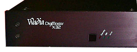
Unlike its big brother, the Wadia 2000, the X-32 is a typical-looking slim black box. The 3/16"-thick front panel holds three square pushbutton switches, accompanied by LEDs indicating the respective switch's position. The left-most pushbutton activates the unit by selecting either the 44.1kHz or 48kHz input. A "Standby" indicator illuminates if neither input is selected. When taken out of Standby mode, the unit will automatically recognize and decode the input sampling frequency. The center switch inverts polarity (in the digital domain), with a red LED to indicate absolute phase reversal. The right switch selects between inputs, two coaxial and one optical. Again, a row of LEDs indicates which input is selected. The "A" input is automatically selected upon power-up. Interestingly, the small, square LEDs and their nomenclature are slanted at about 45° with respect to the front-panel top and bottom. No power on/off switch is provided. Instead, the user is encouraged to leave the unit continuously powered. The X-32's rear panel holds an IEC AC power-cord socket and fuse, digital inputs, and analog outputs. In a departure from the standardized RCA jack, the two coaxial digital inputs are BNC connectors. The BNC connector, found on oscilloscope inputs and some professional digital audio equipment, is far superior to the RCA jack for connection security and longevity. However, one drawback is that the consumer is forced to use the RCA-to-BNC cable supplied with the X-32. The third digital input is via a standard TOSLINK optical input, also called an EIAJ input because of the Electronic Industry Association of Japan's endorsement of this connector. Analog output is provided on a stereo pair of gold-plated Tiffany RCA jacks.
Chassis construction is 16-gauge steel, bent to form the front, back, and sides. A U-shaped steel cover forms the top and sides of the X-32 and is held in place by 16 hex-head screws that screw directly into the chassis, rather than into pem-nuts. In general, I found the X-32's fit and finish adequate, but inferior to many digital processors, including less expensive units. The X-32 comes with an unusual warranty: one year parts and labor at no cost, and during years two through three, Wadia will repair the X-32 with a maximum cost of $200. Incidentally, the owner's manual is also unusual. Its terse style, highly technical content, and layout are reminiscent of military specification documentation.
Moving on to the inside, all the X-32's circuitry—power supply, analog, and digital sections—are on a single circuit board. The power supply consists of a single toroidal transformer, two diodes forming what appears to be a half-wave rectifier, a small DIP full-wave rectifier, three electrolytic filter caps, and eight TO-220–type three-pin voltage regulators (with 1µF output caps) distributed throughout the pcb.
The analog output section is a monolithic version of Wadia's "Sledgehammer" output circuit used in the 2000 Decoding Computer. These chips are two 8-pin DIPs (Dual In-line Package) located between the DACs and pcb jumpers to the analog outputs. The "Sledgehammer" circuit is named because of its ability to drive large amounts of current (400mA peak) into low-impedance loads with a high slew rate of 1300V/µs. For comparison, the Wadia 2000's Sledgehammer output driver is an IC used in conjunction with high-quality passive components. I had a chance to hear the 2000 with and without the Sledgehammer, and found it greatly improved the 2000's performance. Whether the IC version in the X-32 can match the mostly discrete circuit is another question. Wadia claims that putting the passive components on the chip substrate improves performance by reducing temperature tracking differences.
Although I found this quite funny, his reaction exemplifies the quandary of trying to keep pace with the rapidly changing technology of the late 20th century. As the field of audio recording and reproduction becomes more and more sophisticated, we are forced to learn new terminology, new concepts, and, significantly, a new lexicon as we make the transition from analog to digital technology. Where we once discussed VTA, wow and flutter, and compliance, a contemporary audio conversation is more likely to include such terms as EPROMs, jitter, MIPS, and DSP. Today's audio jargon reflects the huge impact computer technology has had on audio equipment.
This revolutionary change really hit home as I was writing the technical description of the Wadia X-32 Digital Decoding Computer. The X-32's technical features throw into sharp relief the changing times. I found myself describing programmable gate arrays, Erasable Programmable Read-Only Memory chips, updateable architecture, Digital Signal Processing chips, clock signals, and jitter reduction circuits.
Unlike its big brother, the Wadia 2000, the X-32 is a typical-looking slim black box. The 3/16"-thick front panel holds three square pushbutton switches, accompanied by LEDs indicating the respective switch's position. The left-most pushbutton activates the unit by selecting either the 44.1kHz or 48kHz input. A "Standby" indicator illuminates if neither input is selected. When taken out of Standby mode, the unit will automatically recognize and decode the input sampling frequency. The center switch inverts polarity (in the digital domain), with a red LED to indicate absolute phase reversal. The right switch selects between inputs, two coaxial and one optical. Again, a row of LEDs indicates which input is selected. The "A" input is automatically selected upon power-up. Interestingly, the small, square LEDs and their nomenclature are slanted at about 45° with respect to the front-panel top and bottom. No power on/off switch is provided. Instead, the user is encouraged to leave the unit continuously powered. The X-32's rear panel holds an IEC AC power-cord socket and fuse, digital inputs, and analog outputs. In a departure from the standardized RCA jack, the two coaxial digital inputs are BNC connectors. The BNC connector, found on oscilloscope inputs and some professional digital audio equipment, is far superior to the RCA jack for connection security and longevity. However, one drawback is that the consumer is forced to use the RCA-to-BNC cable supplied with the X-32. The third digital input is via a standard TOSLINK optical input, also called an EIAJ input because of the Electronic Industry Association of Japan's endorsement of this connector. Analog output is provided on a stereo pair of gold-plated Tiffany RCA jacks.