| Columns Retired Columns & Blogs |
Spendor S100 loudspeaker Measurements
Sidebar 3: Measurements
Footnote 1: The microphone's own deviation from an on-axis flat response has been subtracted from the curves in figs.2, 3, and 4, but not from the three-dimensional cumulative spectral-decay plot in fig.8.—John Atkinson
I use a mixture of nearfield, in-room, and quasi-anechoic FFT measurement techniques (using primarily DRA Labs' MLSSA system with a B&K 4006 microphone calibrated to be flat when used on-axis up to 30kHz—see "Follow Up," October 1991, Vol.14 No.10—plus an Audio Control Industrial SA-3050A 1/3-octave spectrum analyzer with its own microphone) to investigate factors that might explain the sound heard. The speaker's impedance phase and amplitude were measured using the magazine's Audio Precision System One.
As shown by the impedance plot (fig.1), the S100 is an easy load for an amplifier to drive, dropping to a minimum value of 5.7 ohms in the upper bass and remaining pretty much above 8 ohms everywhere else. Coupled with the high voltage sensitivity—I measured approximately 89dB/W/m—the S100 will go loud even with moderately powered tube amplifiers. The port tuning is revealed by the trough centered on 24Hz, which might suggest excellent low-frequency extension.

Fig.1 Spendor S100, electrical impedance (solid) and phase (dashed). (2 ohms/vertical div.)
However, looking at the individual responses of the woofer and port as measured in the nearfield (fig.2)—ie, with the microphone capsule almost touching the dustcap in the former instance—reveals that the S100 has somewhat of an overdamped alignment, which would contribute to the speaker's subjective feeling of "tight" bass. The woofer starts to roll out below 75Hz or so, with the twin ports gradually taking over below that frequency. Though these curves suggest an early, gentle rolloff in the bass under anechoic conditions, this translates in-room, with the normal boundary reinforcement, to effective extension to 30Hz or so, as shown in the spatially averaged response (fig.3). (This curve is the average of 20 1/3-octave spectrum measurements each of left and right speakers taken individually across a 6' by 2' window centered on, and slightly weighted to, the listening seat. This spatial averaging minimizes the effect of room standing waves on the curve and proves to give a measured response that correlates well with a speaker's perceived balance.)
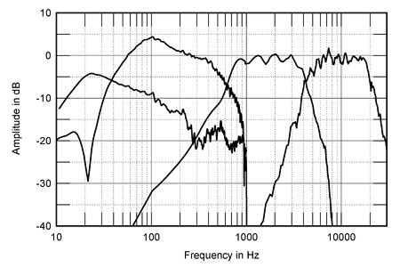
Fig.2 Spendor S100, acoustic crossover on tweeter axis at 44", corrected for microphone response, with the nearfield woofer and port responses plotted below 300Hz and 1kHz, respectively.
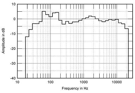
Fig.3 Spendor S100, spatially averaged, 1/3-octave in-room response driven by Mark Levinson No.23.5.
Note, however, the boost in the upper-bass region in fig.3; I was unable to get completely rid of this effect no matter where I placed the speakers or what amplifier I used, and it undoubtedly contributes to my feeling that the S100 has a "powerful" bass and a warm balance. This, of course, would be less evident in a room significantly larger than mine.
Fig.4 shows the S100's quasi-anechoic response on the tweeter axis, averaged across a 30 degrees horizontal window to eliminate the effect of microphone-position-dependent interference effects (footnote 1). Superbly flat in the main, there is some unevenness between 800Hz and 3kHz which might correlate with the slight forwardness noted in the auditioning. This forwardness can also be seen in the in-room balance (fig.3).
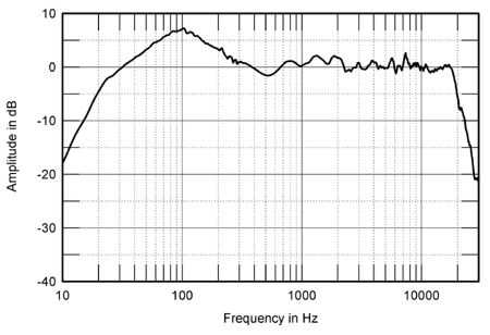
Fig.4 Spendor S100, anechoic response on tweeter axis at 44", averaged across 30 degrees horizontal window and corrected for microphone response, with the complex sum of the nearfield woofer and port responses.
Looking at the responses of the individual drive-units (fig.2) reveals this region to be that handled by the midrange unit. It might be possible that this driver is a little more sensitive than necessary; alternatively, it may have too wide a dispersion at the lower end of its passband. Fig.5 shows the differences in response brought about by listening 7.5 degrees, 15 degrees, and 30 degrees horizontally off the HF-axis: certainly, the midrange unit does start to get peaky in the 1kHz region more than 15 degrees off-axis, which would mean that the reverberant sound in the room would be somewhat accentuated in this region compared with above or below. (Using a driver into the region where its diameter becomes of the order of the wavelength of the sound it is producing will narrow the system's dispersion accordingly in this region.) Whether this would be audible or not would depend on how absorbent the side walls were, how close the listener is to the speakers, and how "dead" the room was in general.
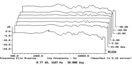
Fig.5 Spendor S100, lateral response family at 44", normalized to response on tweeter axis, from back to front: differences in response 30 degrees-7.5 degrees off-axis, reference response, differences in response 7.5 degrees-30 degrees off-axis.
Fig.6 shows a similar group of curves in the vertical plane, again normalized to the tweeter-axis response. These show the difference in response ranging from with the microphone level with the "Spendor" badge between the tweeter and the woofer to that with the mike 6" above the cabinet top. These curves suggest that the higher up you listen, the more you will perceive a suckout in the crossover region between the tweeter and midrange unit, which will lend the S100's balance a somewhat threadbare quality. The most neutral treble balance will be obtained with the listener level with the tweeter or just below it, which means that to obtain a typical 36" height for the listener's ears from the ground, reasonably high stands, 18" or so, will be required. (These would make the speaker look a little top-heavy, however.)
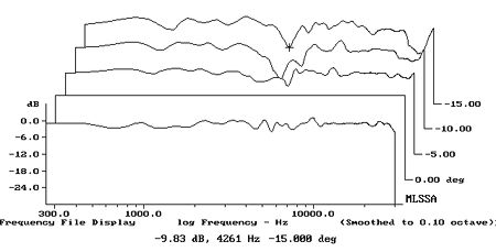
Fig.6 Spendor S100, vertical response family at 44", normalized to response on tweeter axis, from back to front: differences in response 15 degrees-5 degrees above axis, reference response, difference in response 5 degrees below axis
Turning to the time domain, fig.7 shows the S100's impulse response on the HF axis, while fig.8 shows the step response, suggesting that the HF unit and woofer are connected in positive acoustic polarity, the midrange in negative polarity, which gives the best frequency-domian integration of the drive-unit outputs. Fig.9 show how the decay of the impulse response translates to the frequency domain, the so-called "waterfall" plot. There is a little bit of hash at the bottom of the tweeter passband and some garbage in the 1kHz region, perhaps due to reflections of the sound from the edges of the grille, but the plot is otherwise reasonably clean. Looking at the individual drive-units (not shown) reveals the HF hash to be due to the tweeter, while the midrange unit has a well-damped resonant mode at 2.9kHz, this corresponding to the uppermost of the three peaks in its response in fig.4.
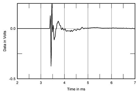
Fig.7 Spendor S100, impulse response on tweeter axis at 44" (5ms time window, 30kHz bandwidth).
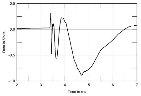
Fig.8 Spendor S100, step response on tweeter axis at 44" (5ms time window, 30kHz bandwidth).

Fig.9 Spendor S100, cumulative spectral-decay plot at 44" (0.15ms risetime).
The woofer's cumulative spectral-decay plot, with the impulse response taken in the nearfield, revealed no aberrant behavior toward the top of its passband that might correlate with the feeling of lower-midrange congestion. That of the port, however, did reveal a couple of resonant modes at 215Hz and 290Hz, the first being the "corner" frequency of the port trace in fig.2. Listening to the cabinet walls with a stethoscope while driving the speaker with a swept sinewave tone did reveal significant enclosure liveliness between 130 and 245Hz, with a back-panel and lower side-panel mode present at 215Hz. It's possible that this behavior might correlate with the tendency for piano tone to acquire woodiness noted during the auditioning, as well as with the slight degree of congestion in this region. But again, it might not.—John Atkinson
Footnote 1: The microphone's own deviation from an on-axis flat response has been subtracted from the curves in figs.2, 3, and 4, but not from the three-dimensional cumulative spectral-decay plot in fig.8.—John Atkinson
- Log in or register to post comments
