Sidebar 3: Measurements
I measured the performance of one of the Parasound JCA100 Tribute's with my Audio Precision SYS2722 system. I preconditioned the amplifier by operating it at one-eighth the specified power into 8 ohms for 30 minutes with the bias of the output stage set to Normal. At the end of this time, the temperature of the side-mounted heatsinks, measured with an infrared thermometer, was 111.1°F (43.9°C) and that of the top panel 95.0°F (35.0°C). An amplifier with a class-A output stage runs hottest when idling, so I remeasured the temperatures the next day, after the amplifier had been turned on for a couple of hours but not playing music. Both the heatsinks and the top panel were hotter, at 118.9°F (48.3°C) and 107.1°F (41.6°C), respectively. This amplifier needs plenty of ventilation
The Parasound's voltage gain into 8 ohms was almost identical to that of the Halo JC 1+. Set to Normal, the gain measured 29.25dB from both the balanced and unbalanced inputs. Switching the gain to Low reduced both gains by 6.3dB. The amplifier preserved absolute polarity (ie, was noninverting) with both balanced and unbalanced input signals. (The XLR jack is wired with pin 2 hot.) Although slightly lower than specified, the balanced input impedance was still very high, at 91k ohms at 20Hz and 1kHz, dropping to 86k ohms at 20kHz. The unbalanced input impedance was 44k ohms at low and middle frequencies and 34.4k ohms at the top of the audioband.
Footnote 1: Parasound's Sheriff said that the JCA100 operates in class-A into 8 ohms all the way to clipping and that into 4 ohms, the class-A cutoff is at approximately 50W.
Footnote 2: See fig.3 here.
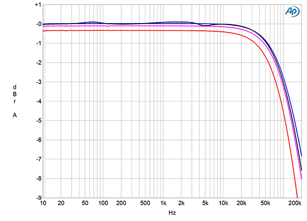
Fig.1 Parasound JCA100, frequency response at 2.83V into: simulated loudspeaker load (gray), 8 ohms (blue), 4 ohms (magenta), 2 ohms (red) (1dB/vertical div.).
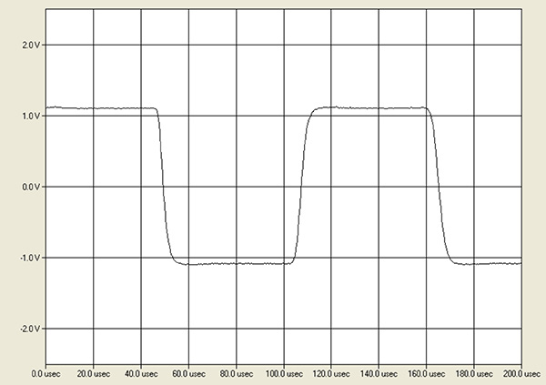
Fig.2 Parasound JCA100, small-signal 10kHz squarewave into 8 ohms.
The Parasound's output impedance, including the series impedance of 6' of spaced-pair loudspeaker cable, was a low 0.05 ohm at 20Hz and 1kHz, increasing slightly to 0.1 ohm at 20kHz. The modulation of the amplifier's frequency response, due to the Ohm's law interaction between this source impedance and the impedance of our standard simulated loudspeaker, was negligible, at ±0.1dB (fig.1, gray trace). The response into an 8 ohm resistive load (fig.1, blue trace) was flat to 20kHz and down by 3dB at 100kHz, which correlates with the JCA100's superb reproduction of a 10kHz squarewave (fig.2). Commendably, the squarewave had no overshoot or ringing.
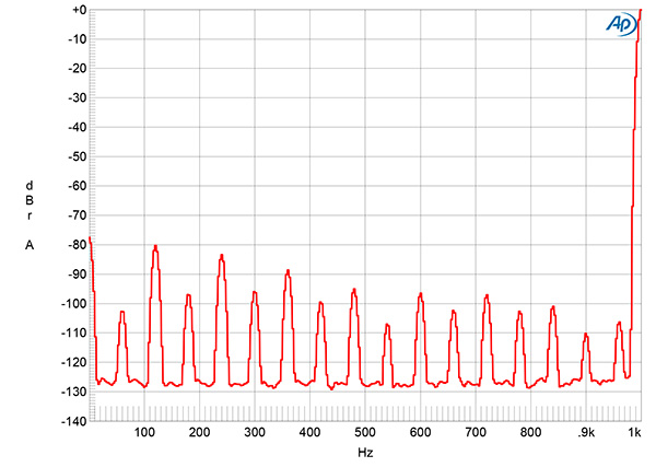
Fig.3 Parasound JCA100, spectrum of 1kHz sinewave, DC–1kHz, at 1W into 8 ohms (left channel blue, right red, linear frequency scale).
Measured with either the balanced or unbalanced inputs shorted to ground, the gain set to High, and the bias set to Normal, the amplifier's unweighted, wideband signal/noise ratio ref. 1W into 8 ohms was not as good as that of the Halo JC 1+, at 65.75dB compared with 75.8dB. This ratio improved to 76.4dB when the measurement was restricted to the audioband and to 85.5dB when A-weighted, the last equivalent to 105.5dB when referenced to the amplifier's specified clipping power. The lower S/N ratio is due to even-order harmonics of the 60Hz power-supply frequency that were present in the Parasound's low-frequency noisefloor (fig.3), the highest of which is the second (120Hz) at –80dB (0.01%). (This spectrum was taken using the amplifier's balanced input and was the same whether the Audio Precision's XLR output was grounded or floating.) These spuriae, which were slightly higher in level in the second amplifier's noisefloor, will be due to a nonzero impedance from the signal ground to the true ground somewhere in the circuit. It is fair to note that I couldn't hear any hum with my ear close to the speakers' woofers.
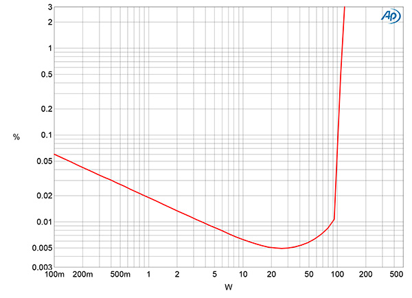
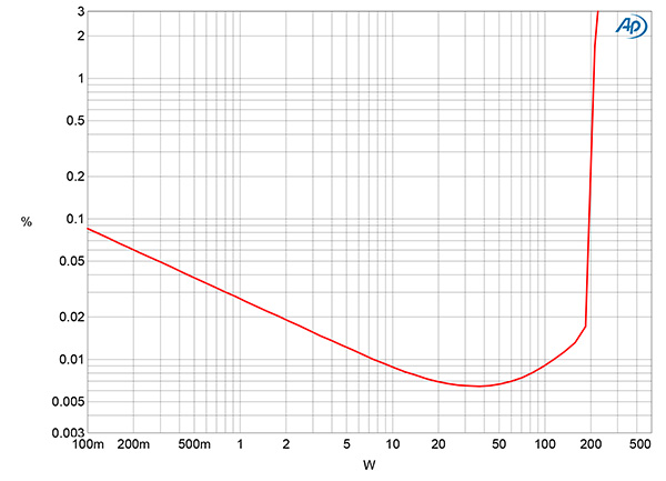
Fig.4 Parasound JCA100, distortion (%) vs 1kHz continuous output power into 8 ohms.
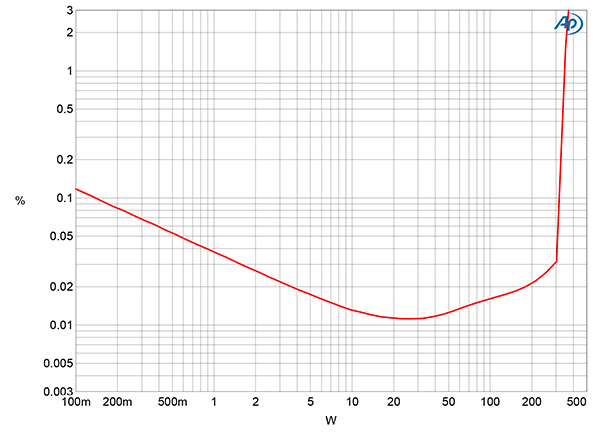
Fig.5 Parasound JCA100, distortion (%) vs 1kHz continuous output power into 4 ohms.
Fig.6 Parasound JCA100, distortion (%) vs 1kHz continuous output power into 2 ohms.
The JCA100's specified maximum power is lower than that of the JC 1+, at 100W into 8 ohms and 200W into 4 ohms (both equivalent to 20dBW), both powers specified at 0.15% distortion. Using Stereophile's definition of clipping, which is when the output's percentage of THD+noise reaches 1%, the Parasound exceeded its specified powers into both impedances. It clipped at 115W into 8 ohms (20.6dBW, fig.4) and 205W into 4 ohms (20.1dBW, fig.5) (footnote 1). The amplifier's maximum power into 2 ohms isn't specified, but I measured 330W into that load at 1% THD+N (19.116dBW, fig.6).
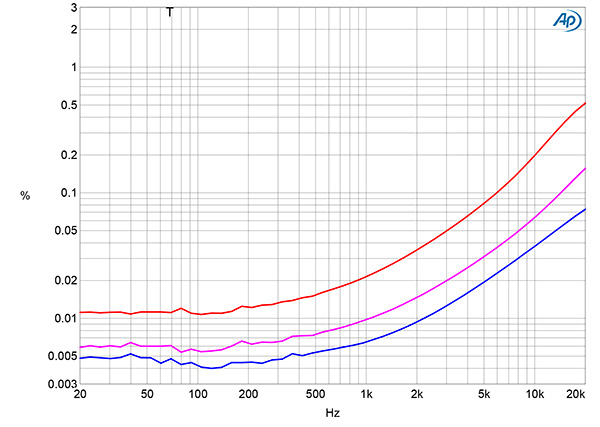
Fig.7 Parasound JCA100, THD+N (%) vs frequency at 20V into: 8 ohms (blue), 4 ohms (magenta), 2 ohms (red).
The downward slope of the traces in figs.4–6 suggests that the measured THD+N percentage was dominated by noise below 30W. I therefore examined how the percentage of THD+N changed with frequency at 20V, which is equivalent to 50W into 8 ohms, 100W into 4 ohms, and 200W into 2 ohms. Even though these powers are only a few dB below the Parasound's maximum output into these loads, the THD+N was very low in the bass and midrange into 8 and 4 ohms (fig.7, blue and magenta traces). The percentage rose both into 2 ohms (red trace) and at higher frequencies. The latter will be due to the circuit having a relatively limited open-loop bandwidth (footnote 2).
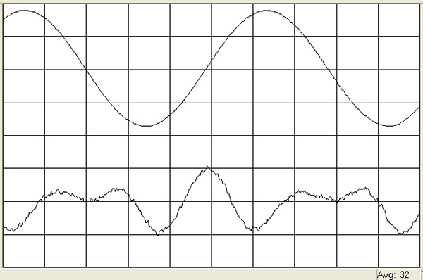
Fig.8 Parasound JCA100, 1kHz waveform at 50W into 8 ohms, 0.0066% THD+N (top); distortion and noise waveform with fundamental notched out (bottom, not to scale).
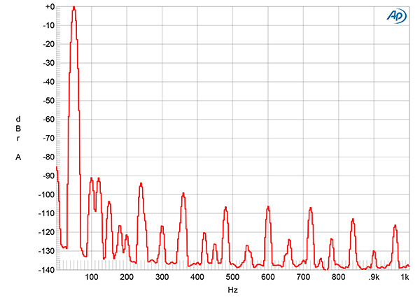
Fig.9 Parasound JCA100, spectrum of 50Hz sinewave, DC–1kHz, at 50W into 8 ohms (linear frequency scale).
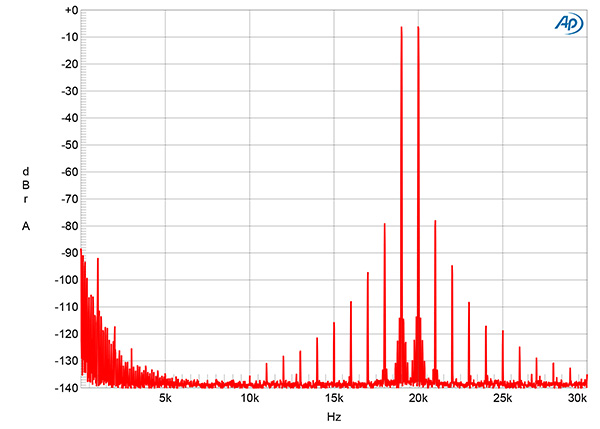
Fig.10 Parasound JCA100, HF intermodulation spectrum, DC–30kHz, 19+20kHz at 100W peak into 4 ohms (linear frequency scale).
The JCA100's distortion was predominantly the subjectively innocuous second and third harmonics (fig.8), and even at the high power used to examine the distortion spectrum (fig.9), the third and higher harmonics are below the levels of the supply-related spuriae. The second harmonic lies at a low –90dB in this graph (0.003%) and didn't rise in level when I reduced the load impedance to 4 ohms. When the amplifier drove an equal mix of 19 and 20kHz tones at 100W into 4 ohms (fig.10), the second-order difference product at 1kHz lay below –90dB, and though higher-order intermodulation products were present, these all lay at or below –80dB (0.01%).
As I wrote about the Parasound Halo JC 1+, it is safe to say that the JCA100 Tribute's distortion signature will have no effect on the amplifier's sonic character.—John Atkinson
Footnote 1: Parasound's Sheriff said that the JCA100 operates in class-A into 8 ohms all the way to clipping and that into 4 ohms, the class-A cutoff is at approximately 50W.


