| Columns Retired Columns & Blogs |
Audio Basics: A Is For Ampere Page 4
Separating AC and DC
Some resistors have much higher resistance to current flow in one direction than in the other. When they do, we cease to call them resistors and refer to them as diodes or rectifiers because they put things right. (It doesn't make sense to me either.) Their main application in audio is the conversion of the household AC supply into DC, which is needed for amplification.
Footnote 7: Strictly speaking, the correct term is reactance, but it is the capacitor's impedance (reactance plus its internal series resistance) which concerns us here.
Some resistors have much higher resistance to current flow in one direction than in the other. When they do, we cease to call them resistors and refer to them as diodes or rectifiers because they put things right. (It doesn't make sense to me either.) Their main application in audio is the conversion of the household AC supply into DC, which is needed for amplification.
One rectifier, in series with the AC supply, will pass every half cycle of the AC input but will block the other half (fig.5). Amazingly, this is called half-wave rectification. To get DC from both halves of the AC input cycle (full-wave rectification), we must use at least two rectifiers in conjunction with a "balanced" AC input, or four of them in what is called a bridge circuit. In the balanced configuration (fig.6), the AC inputs (from a transformer) are in reverse-phase---one rectifier is passing current when the other isn't. In the bridged configuration (fig.7), DC is passed regardless of which way the AC input is polarized.
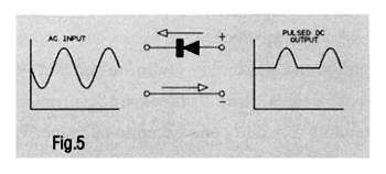
Fig.5 A half-wave rectifier passes current only during each half of the AC input cycle.
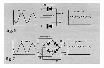
Fig.6 A balanced full-wave rectifier passes current in the same direction regardless of the input polarity. The input must be from a center-tapped transformer winding. Fig. 7 A bridge rectifier delivers mush the same output as a balanced full-wave type, but does it from an unbalanced AC source.
Capacitors
This is a pair of large metal surfaces (plates) with a very thin insulating layer (called a dielectric) between them. Its peculiarity is that it can pass an alternating-current signal while blocking out DC.
When DC is applied to the plates, electrons spread out all over one and drain off from the other. While this is happening, the capacitor draws electrons from the negative source and feeds them to the positive source, just as if the circuit consisted of a wire instead of two insulated plates. But there is a limit to the amount of electron "charge" these plates can hold---related to the plates' capacitance, or "C"---and when they reach that limit, electron flow tapers off and then ceases. Even with the DC still applied to it, no more current will pass. If you now disconnect the capacitor from the circuit, it will hold that charge for some time, until it gradually dissipates, resulting in leakage through the dielectric. If, before that time, you bridge the capacitor with a wire, it will discharge with a spark and a small snap.
Let's say, though, that the applied DC voltage reverses polarity before the capacitor is fully charged. It will promptly start discharging, passing electrons in the opposite direction through the circuit until the capacitor either reaches full charge in the opposite direction or the applied polarity reverses again. If the polarity reversals continue to occur faster than the capacitor can become fully charged, it will pass them almost as if it were a wire, but will steadfastly refuse to pass any DC that is applied to it.
If we graph the relationship between charge state and time, we will see that charging starts very rapidly, then tapers off increasingly rapidly as the capacitor approaches full charge (fig.8). The discharge cycle is exactly the same, but in the opposite direction. That is, it's a mirror image of the charge curve. This is why a capacitor is an almost perfect conductor at very high AC frequencies, and becomes less so (that is, its "impedance" or resistance to AC flow increases) with falling frequency (footnote 7). This dependence of a capacitor's impedance on the frequency of an AC signal allows us to do interesting things at different audio frequencies. Used in conjunction with a current-limiting resistor to slow down its charge/discharge time (fig.9), a capacitor can boost or attenuate treble while leaving lower frequencies alone, it can boost or attenuate bass without affecting higher frequencies, or it can be used to provide a DC voltage source free from any unwanted AC content, like line noise or the 60Hz or 120Hz power-supply ripple that results from the half-wave or full-wave rectification described above.
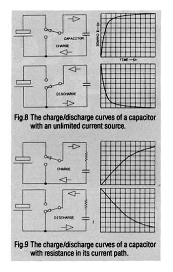
Fig.10 illustrates one such application. This is just like the voltage divider we looked at before except that the lower resistor has been replaced by a capacitor. This RC network will divide the incoming signal voltage according to its frequency, with the attenuation increasing with increasing frequency. The response curve straightens out at the point where the capacitor's impedance equals the resistor value, and the response continues flat below that. The transition "knee" point can be at any frequency, depending on the choice of resistance and capacitance values. A simple way of figuring it is by dividing the two known values (resistance and frequency, for example) into 160,000.

Fig.10 The voltage divider of fig. 3 with a capacitor replacing the bottom resistor becomes a high frequency rolloff (low-pass) filter. The 3dB attenuation frequency occurs where the AC resistance of the capacitor equals the DC resistance of the resistor.
Footnote 7: Strictly speaking, the correct term is reactance, but it is the capacitor's impedance (reactance plus its internal series resistance) which concerns us here.
- Log in or register to post comments
