AC on DC
This isn't a kinky sexual situation, it's what we end up with at the output of an amplifying stage. Consider: The input signal, representing soundwaves, is alternating current, varying positively and negatively above and below zero voltage. But because an amplifying device can only pass current in one direction, its output signal is not AC, it's varying-current DC. Fig.13 shows what it would look like if we plotted output voltage against time. Note that the sinewave has no zero-voltage point on the vertical scale. Instead, it is superimposed on a DC voltage---called a DC offset---of 10V, about which it varies by ±5V above and below that 10V. The signal voltage fluctuates from +5V to +15V, but the electron flow never changes direction; it just varies in current, so it should be obvious that we can't use a rectifier to separate this audio signal from its DC offset. But we can use a capacitor, and usually, we must.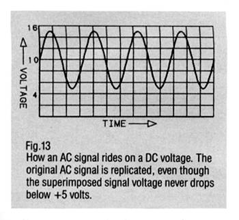 Since an increase in electrons at the gate, a voltage that becomes more negative, tends to inhibit current flow through an amplifying device, a large enough negative voltage there will block all current flow through it, causing it to clip the bottoms from the input signal or, worse, cut off its current flow completely. At the other extreme, too few electrons---too much positive polarity---at the gate will cause the device to pass its maximum amount of current, clipping off the signal's positive peaks and, usually, causing it to overheat too. Somewhere between those extremes is a range of input polarity swings that will produce the lowest signal distortion, and that's what designers aim at. Which is why a "blocking" capacitor is usually put between one amplifying stage and the next. This strips the DC offset from the first stage's output, leaving just the AC voltage fluctuating around 0V, so the designer can optimize the DC offset (called a "bias" when it is introduced intentionally) that is "seen" by the following stage. Unfortunately, capacitors in the signal path tend to degrade the sound, which is why some designers choose to omit them altogether. This requires really tricky circuit design, because without interstage blocking capacitors to supply DC-free signal to each stage, each one must be "floated" by a specific amount above the amplifier's negative ground potential in order to offset the offset from its preceding stage. Then all sorts of regulation must be used in order to ensure that a slight current drift in an early stage doesn't cause a woofer-fryingly large DC offset at the amplifier's output.
Voltage Amplifiers, Power Amplifiers
Since an increase in electrons at the gate, a voltage that becomes more negative, tends to inhibit current flow through an amplifying device, a large enough negative voltage there will block all current flow through it, causing it to clip the bottoms from the input signal or, worse, cut off its current flow completely. At the other extreme, too few electrons---too much positive polarity---at the gate will cause the device to pass its maximum amount of current, clipping off the signal's positive peaks and, usually, causing it to overheat too. Somewhere between those extremes is a range of input polarity swings that will produce the lowest signal distortion, and that's what designers aim at. Which is why a "blocking" capacitor is usually put between one amplifying stage and the next. This strips the DC offset from the first stage's output, leaving just the AC voltage fluctuating around 0V, so the designer can optimize the DC offset (called a "bias" when it is introduced intentionally) that is "seen" by the following stage. Unfortunately, capacitors in the signal path tend to degrade the sound, which is why some designers choose to omit them altogether. This requires really tricky circuit design, because without interstage blocking capacitors to supply DC-free signal to each stage, each one must be "floated" by a specific amount above the amplifier's negative ground potential in order to offset the offset from its preceding stage. Then all sorts of regulation must be used in order to ensure that a slight current drift in an early stage doesn't cause a woofer-fryingly large DC offset at the amplifier's output.
Voltage Amplifiers, Power Amplifiers
There are two kinds of amplification: voltage and power. In voltage amplification, the only thing that matters is how much higher the output voltage is than the input voltage. (This is called voltage gain, and is expressed as a simple multiple: for example, a gain of 4 is when the output voltage is 4 times the input voltage.) In power amplification, the object is to deliver a requisite amount of current along with the voltage so that useful work can be done. The difference lies in the way the active device is used. For pure voltage amplification, the active device passes only as much current as is needed to provide enough amplified signal at the output to drive the next amplifying stage---typically 1 milliampere (1mA, or 1/1000 of an amp) for a transistor. In power amplification, the tube or transistor has a humongous current-carrying capacity to begin with, and the input voltage is used to control this just as with a voltage amplifier. The difference between voltage amplification and power amplification lies only in the amount of current (density of electron flow) that is being gated. Fig.14, while graphically incorrect (there's no such thing as a fat sinewave), will help to give a conceptual insight into the difference.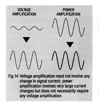 Since power is the measure of work done during a period of time, it must involve a load of some kind, and in audio the load is a loudspeaker whose impedance is typically in the range of 8 ohms. The amplifier's power capability is a statement of how much power it can deliver into that load, usually without exceeding a certain measured distortion, typically 1% (ie, the difference between the shapes of the input and output waveforms is no more than one-hundredth of the latter). When the amplifier's power capability is exceeded, the output voltage cannot increase any more, and the tops (and usually also the bottoms) of the signal start getting shorn off (fig.15). The resulting sharp corners on the signal represent extra HF energy, which is why a low-powered amplifier that overloads frequently is much more likely to destroy tweeters than one which is powerful enough to burn out the entire speaker system but (for that reason) rarely goes into clipping.

This isn't a kinky sexual situation, it's what we end up with at the output of an amplifying stage. Consider: The input signal, representing soundwaves, is alternating current, varying positively and negatively above and below zero voltage. But because an amplifying device can only pass current in one direction, its output signal is not AC, it's varying-current DC. Fig.13 shows what it would look like if we plotted output voltage against time. Note that the sinewave has no zero-voltage point on the vertical scale. Instead, it is superimposed on a DC voltage---called a DC offset---of 10V, about which it varies by ±5V above and below that 10V. The signal voltage fluctuates from +5V to +15V, but the electron flow never changes direction; it just varies in current, so it should be obvious that we can't use a rectifier to separate this audio signal from its DC offset. But we can use a capacitor, and usually, we must.
Since an increase in electrons at the gate, a voltage that becomes more negative, tends to inhibit current flow through an amplifying device, a large enough negative voltage there will block all current flow through it, causing it to clip the bottoms from the input signal or, worse, cut off its current flow completely. At the other extreme, too few electrons---too much positive polarity---at the gate will cause the device to pass its maximum amount of current, clipping off the signal's positive peaks and, usually, causing it to overheat too. Somewhere between those extremes is a range of input polarity swings that will produce the lowest signal distortion, and that's what designers aim at. Which is why a "blocking" capacitor is usually put between one amplifying stage and the next. This strips the DC offset from the first stage's output, leaving just the AC voltage fluctuating around 0V, so the designer can optimize the DC offset (called a "bias" when it is introduced intentionally) that is "seen" by the following stage. Unfortunately, capacitors in the signal path tend to degrade the sound, which is why some designers choose to omit them altogether. This requires really tricky circuit design, because without interstage blocking capacitors to supply DC-free signal to each stage, each one must be "floated" by a specific amount above the amplifier's negative ground potential in order to offset the offset from its preceding stage. Then all sorts of regulation must be used in order to ensure that a slight current drift in an early stage doesn't cause a woofer-fryingly large DC offset at the amplifier's output. There are two kinds of amplification: voltage and power. In voltage amplification, the only thing that matters is how much higher the output voltage is than the input voltage. (This is called voltage gain, and is expressed as a simple multiple: for example, a gain of 4 is when the output voltage is 4 times the input voltage.) In power amplification, the object is to deliver a requisite amount of current along with the voltage so that useful work can be done. The difference lies in the way the active device is used. For pure voltage amplification, the active device passes only as much current as is needed to provide enough amplified signal at the output to drive the next amplifying stage---typically 1 milliampere (1mA, or 1/1000 of an amp) for a transistor. In power amplification, the tube or transistor has a humongous current-carrying capacity to begin with, and the input voltage is used to control this just as with a voltage amplifier. The difference between voltage amplification and power amplification lies only in the amount of current (density of electron flow) that is being gated. Fig.14, while graphically incorrect (there's no such thing as a fat sinewave), will help to give a conceptual insight into the difference.
Since power is the measure of work done during a period of time, it must involve a load of some kind, and in audio the load is a loudspeaker whose impedance is typically in the range of 8 ohms. The amplifier's power capability is a statement of how much power it can deliver into that load, usually without exceeding a certain measured distortion, typically 1% (ie, the difference between the shapes of the input and output waveforms is no more than one-hundredth of the latter). When the amplifier's power capability is exceeded, the output voltage cannot increase any more, and the tops (and usually also the bottoms) of the signal start getting shorn off (fig.15). The resulting sharp corners on the signal represent extra HF energy, which is why a low-powered amplifier that overloads frequently is much more likely to destroy tweeters than one which is powerful enough to burn out the entire speaker system but (for that reason) rarely goes into clipping. 


