In high-end circles, the sonic repute of integrated-circuit op-amps (from "operational amplifier") is, at best, checkered. Of course, the expertise with which they are used and the parts they're used with can make all the difference. For example, my DIY preamplifier design, "AMP-02," published in Hi-Fi News & Record Review in 1989–90, and my earlier (1983–84) AMP-01 (footnote 1), I used the better IC op-amps of the time throughout. Both units were thought to outperform cost-no-object commercial units of the time that employed discrete transistors and even tubes, and only indicate what's possible.
What's an Op-Amp?
Nearly all the integrated circuits used in audio signal paths are general-purpose parts called "operational amplifiers." (See "Integrated Circuits" sidebar.) "Operational" doesn't mean that such amplifiers are not defective, but that, from a mathematical point of view, they're able to perform generic math operations. Amplifying is seen as multiplying; mixing (as in studio consoles) is adding; a balanced input uses subtraction; low-pass filtering is equivalent to integration; etc.
It's important to realize that not all op-amps are ICs, nor must they use transistors. The first "op-amps" were discrete circuits using tubes, and appeared during WWII in order to facilitate Project Tube Alloys—the British contribution to the Allied project to create atomic an weapon before Nazi Germany did. The US wartime invention of the op-amp by John Raggazini built on the "long-tailed pair," a powerful circuit patented in England by Alan Blumlein of EMI for the BBC's world-first TV service of 1936. After the war, George Philbrick made the first commercial op-amps with discrete transistors (see "References" sidebar [1,2]).
Whether IC or discrete, an ideal op-amp would have infinite gain, meaning that it would make an input signal infinitely bigger. Actual op-amps have hugely high gains (from 50,000 × up to 100 million ×)—way above what is of any direct use to audio, and solely over a narrow frequency range; say, up to just 1Hz, or at best 1kHz. Using negative or "regulative" feedback, this seemingly useless narrowband performance can be happily traded against a far wider bandwidth. This bandwidth can be way greater than the audioband, yet still in theory be accompanied both by any practical gain desired, usually between +6dB (×2) up to +30dB (×33), as well as by far greater linearity (lowered distortion and other errors). But not all errors are perfectly canceled.
Op-Amps in Audio
Despite their theoretical appeal, op-amps are easily and widely misused. Some early ones were not fit for serious audio applications, even when used carefully. And the misapplication of op-amps can result in unpleasant or even music-destroying sound. As a result, many audiophiles have been led to believe that IC op-amps are anathema to audio, period.
But even if your replay system contains no ICs, most professional recording since about 1972 has, for better or worse, involved passing the signal through many op-amps long before it reaches your system. Even in today's digital studios, enough of the signal path remains in the analog domain that op-amps are still involved.
A sad thing to ponder is that when you listen to many 1970s recordings (mainly rock music) on one of today's high-resolution, solid-state audio systems, the use of substandard ICs in the recording chain—or the lazy use of less bad ones—is plainly audible, once you know what you're listening for. This has left the world with a legacy of smeared, mangled recordings that, now that more than half of the 20th century's significant musical artists are dead, may never be correctable. In fact, in the four years since this article was first drafted, many musical heroes of my own—including Ian Dury, Tito Puente, Bernard Edwards, Junior Walker, and Johnny "Guitar" Watson—have passed on.
This is the point at which HLOs ("Hard-Line Objectivists"; see sidebar) usually jump in to say that, because every source of recorded music has been processed with op-amps, for someone to say that they can hear the sonic effects of a particular op-amp in a piece of consumer electronics is delusional. If op-amps are supposed to sound "unmusical," they argue, how come this unmusicality doesn't seem to apply when they're used earlier in the chain?
One answer is that the HLOs are thinking in a linear, simplistic "1+2+3" fashion. They fail to grasp that the results can be counterintuitive in a complex system in which iterative processing is used—such as subjecting music to similar reproduction errors again and again, as when the same part is used at several places in the audio chain. Thus, the result of passing a signal through many imperfect stages can be quite different from the sonic effects of any one of those stages. Example: Strident harmonics can develop into a more innocuous, less audible noise. Such noise can also then paradoxically enhance faint details in the mix, acting like dither in digital-land. (A related effect is well known in some branches of science as "stochastic resonance." [3])
Another counterintuitive truth is that measurably poor audio equipment can actually enhance music, should it fortuitously subtract from or nullify a preceding distortion. Thus, two audio wrongs can sometimes make a right. But the safer bet seems to be to begin with a near-perfect path.
A nice feature of op-amp ICs—when socketed rather than soldered directly to the printed circuit board—is that, like tubes, you can swap types or upgrade them more easily than you can discrete transistors (although, as with tubes, caveats apply). The 24 years of work I've done with various professional colleagues with recording rooms, stage sound systems, and domestic setups have convinced me that skilled and musically adept listeners readily hear the upgrading of one or more IC op-amps.
What's also interesting is that, with the modern parts released in the past decade, what's being heard is only just measurable with some of the world's most powerful audio analysis equipment. If you've read anything in the last decade about the leading edges of scientific research into human consciousness, and the holographic, higher-dimensional nature of the reality that mystics, physicists, and brain physicians seem to agree that we "really" live within [4,5], then you might find this disparity easier to comprehend.
Whether many or any of the newer, enhanced ICs (footnote 2) process op-amps appear in today's recording chains is another matter, considering how the pro-audio industry appears to be driven almost solely by the bottom line. This means that old designs that were good in their day continue to dominate the pro-audio field almost a quarter century later. (Texas Instruments' TL071 appeared ca 1976, Philips' NE5534 about 1978.) Their makers have long amortized the design costs and learned the recipe for good yields, so the low prices keep the volume up, which in turn keeps prices low. Better modern ICs have not yet managed to break strongly into this "cartel loop."
Some IC op-amps are multichannel parts, some are duals (in the same way that a 12AX7 vacuum tube is a dual triode), and some are quads (four in a package). Often, you can buy the same specification in single and dual, or single, dual, and quad packs. Dual and quad parts save some space and cost less per channel. It follows that manufacturers of audio products who listen through their balance sheets will tend to use dual and/or quad ICs in their products. And as success in the recording industry appears to be measured by how long the signal path is in your mixing console, dual and quad ICs are essential to cramming enough circuitry into a human-operable space.
Spectral & Other Testing
Since 1990 I have published a number of group reviews [6,7,8,9,10,11] on the measurable performance of IC op-amps for audio, the most recent being an update for UK pro-sound magazine Studio Sound. My op-amp testing had begun with linearity. It would have been easiest to measure the percentage of THD (vs level or frequency) as a means of categorizing sonic quality. However, this is potentially meaningless or even highly misleading [12,13]. Instead, I resolved to concentrate on showing each part's harmonic spectrum. In my experience, this information, however low in level, is far more likely to corroborate with the device-under-test's sonic character, as assessed by others before measurement.
Given manufacturers' propensity to use multichannel parts, I tested the intrinsic crosstalk (footnote 3) of a variety of dual and quad op-amps. (This is perhaps the first time this particular measurement has appeared in any publication.) I first performed a conventional measurement. A single IC test fixture previously established for spectral testing [7] was converted into a dual or quad socket on 1!9/25mm vertical extender leads. Fig.1 shows the circuit diagram; the tested IC's channel 1 (ch.1) operated as a one–op-amp balanced input stage (a differential to single-ended converter) with 0dB, or unity gain/
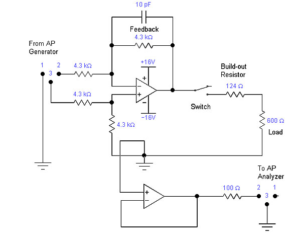
The tests were carried out with two output load conditions (including the feedback resistor) of 4.3k and 600 ohms. The latter is tougher, simulating higher gain and/or heavier output loading. (The switchable 600 ohm load was "built out" with a 124 ohm series resistor so that the overall load, including the 4k3 feedback resistor, is 600 ohms.) Channel 2 (for duals; ch.3 for quads) had its output strapped to its inverting input to give unity gain, with its non-inverting input cleanly connected to ground. An Audio Precision System One Dual Domain analyzer was then connected to the ch.2 output, with the wiring heading diametrically away from ch.1, for best isolation. A ch.1 test input level of 1V RMS was chosen because it provides the lowest-distortion condition for the AP System One.
Manufacturers have long recognized the need for isolation between channels in dual and quad op-amps. A weak point is the shared power connection. Here, the ideally (but rarely wholly) rock-stable supply voltages can be polluted by the signal's demands in one channel. This variation in the supply then bleeds into the other or another op-amp channel. This effect is counteracted by a powerful feature of any op-amp, called "supply-noise rejection," which varies with different models. It's also counteracted by having a highly "active" (low-impedance) power source that instantaneously resists any voltage fluctuations. This approach was used in these channel separation tests, with a highly regulated supply situated within 2"/50mm of the tested IC's pins. This way, I could be sure that the leakage spectra seen were internal, not just an artifact of poor application.
As a precaution, I measured the residual and lab environmental noise present on the undriven channel's output when ch.1 of the dual or quad IC was also undriven (fig.2). The noisier trace of the two, with prominent spikes at 50Hz and 32kHz, occurred when the IC wasn't powered. When it was powered (lower trace), the 50Hz AC line pickup was about –135dB referred to the fundamental, while pickup of the AC harmonics—up to the 20th at 1kHz—was even lower. Therefore, the AC line harmonics would contribute nothing to the test result.
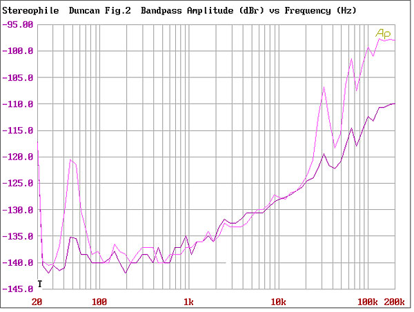
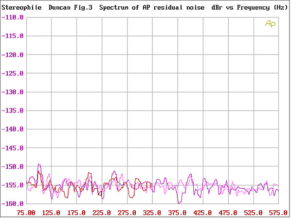
As another precautionary discipline, the AP test set's own residue was logged before, during, and after the testing, with the analyzer input shorted (fig.3). Note that the noise lies almost entirely 150dB below the 1V RMS test signal, excepting the apparent leakage of the second harmonic at 100Hz. This is possibly 100Hz ripple from the AP's own power supply.
Conventional 1/3-octave swept "crosstalk" plots (fig.4) showed that some dual op-amps have a capacitive leakage problem. If the part of the residue that's below –120dB (at 1kHz; and pro-rata below –107dB by 20kHz) is assumed to be purely random noise, then only the behavior of the TI TL072 and TL052 will be of much concern (top two traces). In these two types, the interchannel isolation is degraded to as little as –96dB at 20kHz. The sonic upset that this leads to will be greatest at HF, then in equipment with some number of dual op-amps, and will stand out as added "tizz" where the isolation between stages and channels is otherwise good. It will also be a problem when one channel handles signals that are quite different—or at quite different levels—from the other.
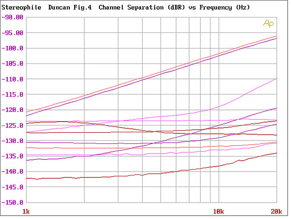
Other ICs had considerably smaller degrees of leakage. The Harris HA5222 had the lowest, but the ranking of those at the lower levels has as much to do with having low noise as with real crosstalk. That's because the noise obscures the view—even in the analyzer's relatively selective, hence noise-free, 1/3-octave–wide bandwidth.
To better see what's really there, a tool that could eke out spectra below the noise floor is required. The solution used here is the same AP test set, working in DSP mode, with its narrower 3Hz bandwidth (a notional 1/11 of an octave at 50Hz), followed by DSP averaging—which gives stochastic-noise–subtraction capabilities (footnote 4). Sixteen samples were averaged by the DSP, which subtracts true, random ("stochastic") noise, and gives a high (better than ±1dB, or 12%) certainty to results as low as 1ppm (one part per million).
I have called this the "Spectral X-Contamination" test. In the configuration used, the AP test set permitted visual resolution of harmonics down to below –150dB, or one part per 30 million. Allowing a minimum 5dB margin above this residue to allow for the errors of interaction and ±1dB of uncertainty, crosstalk figures above –145dB are real and quite reliable.
Harmonic Issues
Before I examine the results of the test, I should briefly explain the general significance of harmonics [14]. The second, fourth, and eighth harmonics are innocuous in one sense, as their octave or multi-octave relationships with the fundamental mean that they are 100% consonant. But their presence, with possibly random phase relations to the fundamental, nonetheless retains the capacity to change the sound's timbre and pitch in ways that may be unpredictable. The third, sixth, and particularly the fifth harmonics might be pleasing in some combinations, relatively innocuous in others, and dissonant in still others. The remaining harmonics (the seventh, ninth, and all above) are almost always highly dissonant, even in tiny quantities—unless you're attuned to Japanese music.
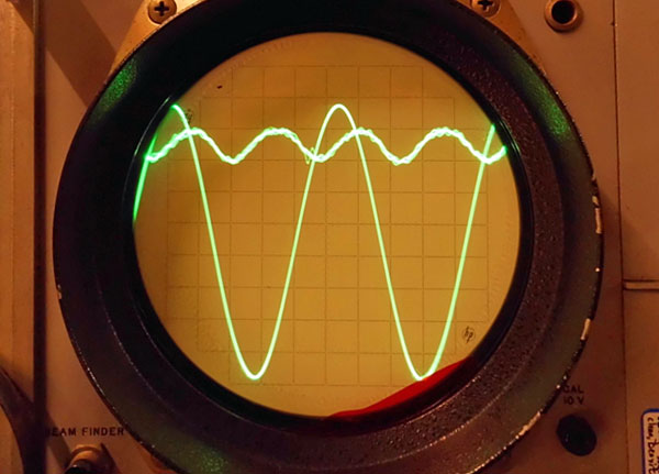
The capacity of harmonics to compound into a morass of intermodulation products is insufficiently regarded by audio engineers. The test stimulus is just one tone, while music can contain hundreds of tones at any instant. Where you see several spikes on each graph, bear in mind that these are for each discrete frequency; at any instant, music will contain dozens if not hundreds of these, as over any period even a single instrument's simplest sound contains multiple harmonics, and hence discrete frequencies, of its own.
It's also helpful to recognize that the different tests for harmonic and intermodulation distortion are all attempts to measure just one thing: nonlinearity. The same nonlinearity that fortuitously makes only the second harmonic dominant can just as easily create other spuriae at non-harmonically related frequencies, if the second harmonic created then interacts with the fundamental or any other harmonics to produce intermodulation products. Thus, a dominant second harmonic in one stage can add third harmonic to the next, as fundamental plus second begets some third harmonic, and so on ad nauseam. In this way, playing music and hearing background grunge is one way a listener can reasonably infer the existence of harmonics that lie below the resolution of even the most powerful test gear!
Footnote 1: "AMP" is an acronym for "Analog Modular Preamplifier"—in part, a playful parody of the English QUAD name, which originally stood for "Quality Unit Amplifier Domestic"!
Footnote 2: It is little realized that IC makers are themselves dependent on fundamental research organizations. Around 1988, Bell Labs licensed its new CB (complementary bipolar) technology, which enabled vastly better-matched, better-performing PNP (bipolar) transistors to be etched into IC circuits. Before, IC designers had been hamstrung by having only decent NPN transistors, whereas discrete circuit designers had been able to use well-matched NPN and PNP transistors since the mid-1960s.
Footnote 3: As opposed to crosstalk caused by the physical (mis)layout of the circuit op-amps are employed in.
Footnote 4: Because the desired signal is self-correlated and the noise is not, summing two measurements increases the wanted signal by 6dB but the noise by only 3dB. Thus, each time the number of averages is doubled, the noise effectively drops by 3dB. This is why, when I perform a MLSSA measurement of its on-axis response to produce a loudspeaker's cumulative spectral-decay plot, I average 128 measurements, which lowers the level of the environmental noise by 21dB.—John Atkinson


