A CD transport/digital processor combination introduces jitter in three ways: 1) the transport puts out a jittered signal; 2) the S/PDIF or AES/EBU interface between the transport and processor creates jitter; and 3) the digital processor adds its own jitter to the clock. These additive factors are largely responsible for the great range in sound quality we hear from different transports and interfaces.
This digital chain offers an opportunity to reduce jitter before it gets to a digital processor. We simply feed a transport's output to a jitter-reduction device and send the presumably low-jitter signal to the digital processor. The intended result is less jitter on the word clock at the digital/analog converter, thus better sound quality.
The first jitter-reduction device was the original Audio Alchemy Digital Transmission Interface (DTI). In my 1993 review and subsequent measurements of the DTI (Vol.16 Nos.1, 5, & 11), I found that it improved the sounds of some transport/processor combinations and degraded the sounds of others. Measurements later revealed that the DTI's output jitter was lower than that of poor transports, but higher than that of the best transports.
Jitter reduction has come a long way since the original DTI—the newest crop of jitter attenuators reviewed here are vastly more sophisticated, and effective. The brand-new DTI Pro provides what Audio Alchemy calls "resolution enhancement," a technique which increases the output word length from the CD's 16 bits to 18 and even 20 bits, reportedly increasing resolution beyond the CD's 16-bit limit. Conversely, the Digital Domain VSP, designed by recording engineer Bob Katz (you've heard Bob's exceptional work on most of Chesky's CDs), includes a sampling-rate converter for professional applications. The Sonic Frontiers UltrajitterBug, a straight jitter attenuator, is the least expensive device in this group.
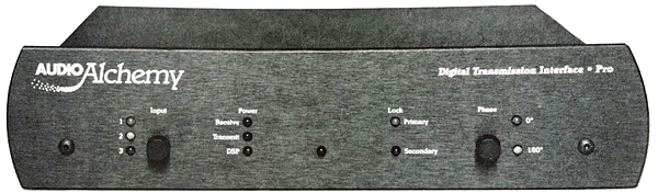
Audio Alchemy DTI Pro
The DTI Pro sports Audio Alchemy's new styling, with a curved-edge front panel and nicer cosmetics. At just 8" wide and 2" high, the Pro is small enough to fit on top of a digital processor or front-loading CD transport. The power supply included with the DTI Pro is Audio Alchemy's Power Station Four, although any Audio Alchemy Power Station will work.
AES/EBU, coaxial, and TosLink inputs and outputs are standard, and an ST-type optical input is offered as an option, replacing the TosLink. If the DTI Pro does its job, the input cable shouldn't make much difference to the sound.
The coaxial input and output jacks are BNC types, which, as true 75 ohm connectors, are the best coaxial connections. If your transport or processor has BNC jacks, use them with the DTI Pro. Audio Alchemy supplies two RCA-to-BNC adapters for those who have RCA inputs and outputs. The rear panel also holds the DC-power input jack and an I2S bus jack for interfacing the DTI Pro to other digital products in the future.
No fewer than ten LEDs adorn the front panel. Starting at the left-hand side, a row of three LEDs indicates which input is selected. The second row of LEDs is labeled "Receive," "Transmit," and "DSP," showing that these circuits are receiving DC power. The next LED pair shows when the DTI Pro is locked to a data source, with the "Secondary" lock LED illuminating when the DTI Pro's second PLL has locked. Finally, a pair of LEDs indicates polarity reversal or no polarity reversal. When the DTI Pro is powered up and locked, it lights up with bright green and red LEDs like a Christmas tree.
Two pushbuttons control absolute polarity and select between the digital inputs. These polarity and input buttons also work together to select the DTI Pro's output word length. By holding the polarity button (marked "Phase") down while pushing the "Input" button, you can select 16-bit output words, 18-bit words, or 20-bit output words. In the 18-bit and 20-bit modes, DTI Pro adds dither to the digital output.
This feature optimizes the DTI Pro's operation for the digital processor it's driving. For example, processors with 18-bit DACs should work best when fed 18-bit words, and processors capable of full 20-bit input and conversion can take advantage of 20-bit input data. Without this feature, an 18-bit digital processor would simply truncate (cut off) the two Least Significant Bits (LSBs) of the 20-bit word, causing distortion (footnote 2).
Note that very few digital processors can pass 20-bit data through their digital filters to the DACs. You may have a processor with 20-bit DACs, but they won't receive the DTI Pro's 20-bit data. Instead, the 20-bit input words are truncated to 18 bits by your processor's digital filter, which then recalculates the 20-bit output words that are sent to the DACs.
Consequently, the DTI Pro may sound its best when in its 18-bit output mode, even though your digital processor has 20-bit DACs. I have on hand a Mark Levinson No.30.5 Reference Digital Processor, which uses the new NPC 5842 filter that will pass 20-bit data. (I'll report on the musical differences between the DTI Pro's output word lengths with different processors later in the listening impressions.)
The DTI Pro's "resolution enhancement" algorithm is run on a Star Semiconductor quad DSP chip driven at 40MHz. A socketed Erasable Programmable Read-Only Memory (EPROM) chip contains the software that tells the DSP chip what to do. Specifically, the algorithm looks at the 16-bit data over a sequence of samples and interpolates (estimates) what data would have been present had the data been encoded with greater than 16-bit quantization. The DSP then adds those lower bits (turning 16-bit words to 18- or 20-bit words) to approximate a signal with higher resolution.
A drawback of this technique is that it works best at low frequencies, and not at all at high frequencies. With a high-frequency waveform, very few samples represent each cycle. Consequently, the algorithm is given much less data from which to interpolate.
I was curious about how resolution enhancement differs from the standard digital filtering found in off-the-shelf oversampling digital filter chips. Those devices take in 16-bit words and output 20-bit words. The extra bits are created from the intermediate calculations performed in the filter. The digital filter may internally process (in the filter's accumulator) the audio samples with very long words, then round-off those long words to 20 bits for output to the DACs. Note that no new information is created by this process. Instead, the technique merely reduces the requantization error added by the filter.
Audio Alchemy claims that their resolution enhancement is very different. The additional bits created by resolution enhancement do contain new information; the bits are calculated by looking at the sample values over a time window, and adding the bits the algorithm guesses would have been there had the signal been of higher resolution. The additional bits created by an oversampling digital filter are, Audio Alchemy says, noise—the result of the finite arithmetic precision in the filter—while the DTI's additional bits are created by interpolation. [I still don't understand how this differs from an oversampling filter, in which, in effect, the filter's low-pass function interpolates the shape of the waveform between the original samples.—John Atkinson.]
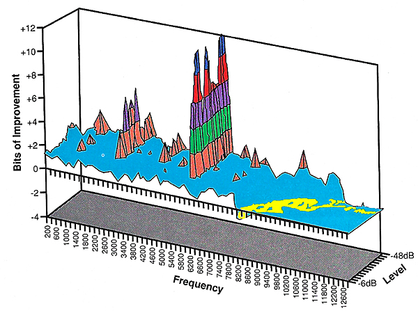
Audio Alchemy provided Stereophile with a three-dimensional plot that AA claims shows the measured resolution improvement afforded by their res technology (fig.A). Note that this graph is not a theoretical model, but the result of an actual measurement made on a DTI Pro with a Sun workstation computer. The plot appears to show about a 2-bit overall improvement in resolution up to 7kHz for high-level signals, and increased resolution to 11kHz with low-level signals. The sharp spikes of very high resolution occur at frequencies at which the algorithm happens to be most efficient. I'd be interested in hearing more about how this measurement was made (perhaps in Audio Alchemy's "Manufacturer's Comment"?).
Because the resolution-enhancement algorithm is contained in a socketed EPROM, upgrading the DTI Pro as new software is developed is simply a matter of changing a chip. Audio Alchemy estimates that future software upgrades will cost between $50 and $75. The master oscillator is also socketed in case Audio Alchemy wants to increase the clock speed driving the DSP chip.
The DTI Pro's jitter-attenuation circuit is based on the ubiquitous Crystal CS8412 input receiver (as was the DTI). But, unlike the DTI, the DTI Pro uses a second Phase Locked Loop (PLL) to reduce jitter in the recovered clock. Remember the "Secondary" lock LED on the front panel? It illuminates when this second PLL has locked. The idea behind dual PLLs is to make the first PLL loose enough (or have a wide enough acceptance window) so that it can lock to a wide range of input frequencies and jitter levels, then feed that recovered clock into a much tighter, precise PLL that generates a final output clock of very low jitter. The second PLL uses a precision Voltage Controlled Crystal Oscillator (VCXO) as a reference. As far as I know, this technique was first used in the Meridian 263 processor.
In addition to reducing the overall amount of jitter, dual PLLs isolate the output clock from incoming signal-correlated jitter. Signal-correlated jitter is jitter on the clock at the same frequency as the music. In fact, it's possible to listen to only the jitter component of the S/PDIF signal and easily identify the music—just from hearing the interface jitter. This signal-correlated jitter is the most pernicious because it's periodic rather than random. (Random jitter is called "white" jitter because of its similarity to white noise.)
Footnote 1: Jitter is such a hot topic that a page in the recent Audio Advisor catalog proclaimed: "Audio Advisor: Your Jitter-Reduction Headquarters."
Footnote 2: The musical effects of truncating the Least Significant Bits are severe: distortion, hardness, glare, grain, and a flat soundstage. This is especially true when chopping a 20-bit word to 16 bits. It seems astonishing now, but the first Sony CD master-tape editors (the DAE-1000 and DAE-1100) truncated 16-bit words from the source to 14 bits whenever the editor's fader was moved from unity gain (no level change). The editor's processor couldn't do the math fast enough on 16-bit words. To make matters worse, it was common practice in those days to "follow the fade"—ie, move the digital editor's fader down as the music decayed at the end of a piece. The result was a horrible, sandpaper-like coarseness on low-level signals, particularly reverberation decay. Sony's DAE-3000, introduced in 1987, corrected this problem, and even added user-selectable dither. Modern Macintosh-based editing systems can now operate on 20-bit data. It's no wonder that today's CDs sound vastly better than those introduced in the first years of the format.


