Our review sample of the Moscode 401HR was fitted with 6H30Pi and 6GU7 tubes. I preconditioned the amplifier by running it for 60 minutes at 67Wpc (one-third the specified power) with both channels driven into 8 ohms. With the amplifier cold, the THD+noise was 0.049%; this rose very slightly to 0.06% with the amplifier fully warmed up. By the end of the preconditioning period the shielded heatsinks were too hot to touch, but the chassis temperature was acceptably low at around 50°C.
The amplifier preserved absolute polarity (ie, was noninverting) and offered a higher-than-usual voltage gain of 29.5dB into 8 ohms. Its input impedance was a usefully high 100k ohms at bass and midrange frequencies, dropping slightly to 79k ohms at the top of the audioband. The output impedance was a little high for a modern solid-state design, at 0.22 ohm at most frequencies and rising a very little, to 0.235 ohm, at 20kHz. This impedance gave rise to ±0.15dB response variations with our standard simulated loudspeaker (fig.1, top trace at 2kHz).
More obvious in fig.1 is the fact that, while the small-signal bandwidth is very wide—the –3dB point into 4 ohms is a high 180kHz—the response does peak by a fraction of a dB above the audioband into higher impedances before rolling off. No peak is apparent into 2 ohms (fig.1, bottom dashed trace), but the –3dB frequency has dropped to 150kHz. This ultrasonic peaking results in a small degree of overshoot with the amplifier's reproduction of a 1kHz squarewave (fig.2), but the 10kHz waveform (fig.3) indicates that the overshoot is well damped and there is no ringing.
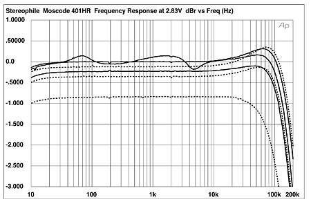
Fig.1 Moscode 401HR, frequency response at 2.83V into (from top to bottom at 2kHz): simulated loudspeaker load, 8, 4, 2 ohms (0.5dB/vertical div., right channel dashed).
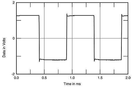
Fig.2 Moscode 401HR, small-signal 1kHz squarewave into 8 ohms.
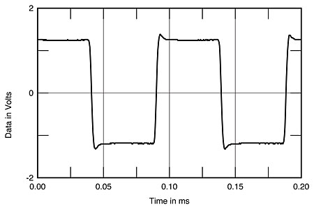
Fig.3 Moscode 401HR, small-signal 10kHz squarewave into 8 ohms.
Channel separation (fig.4) was good rather than great, at 84dB at 1kHz in both directions, this degrading to 63dB at 20kHz due to the usual capacitive coupling. Noise levels were quite low, with an A-weighted signal/noise ratio (ref.1 W into 8 ohms) of 82.5dB. This worsened only slightly, to 77.6dB, with a wideband, unweighted measurement.
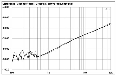
Fig.4 Moscode 401HR, channel separation (10dB/vertical div.).
Fig.5 shows how the THD+noise percentage in the Moscode's output varied with output power and load impedance. The amplifier more than meets its specified power, giving out no less than 250Wpc into 8 ohms (24dBW) and 390Wpc into 4 ohms (22.9dBW) at 1% THD. It faltered into 2 ohms, however, giving out just 130W into this load (15.1dBW) at the same 1% THD point, even with just one channel driven. You can also see from this graph that the THD percentage starts to increase at a much lower power level than with the higher impedances.
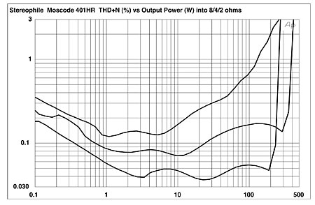
Fig.5 Moscode 401HR, distortion (%)vs 1kHz continuous output power into (from bottom to top at 100W): 8, 4, 2 ohms.
The downward slope below 2–3W of the traces in fig.5 indicates that the measurement is dominated by noise at these power levels. I therefore assessed how the THD+N percentage varied with frequency at a 6V output level, equivalent to 4.5W into 8 ohms. The results are shown in fig.6: again, the 401HR is clearly uncomfortable driving 2 ohms, but the expected rise in THD at high frequencies is lower than I usually see.
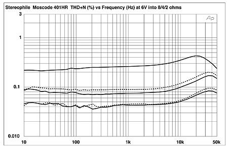
Fig.6 Moscode 401HR, THD+N (%)vs frequency at 6V into (from bottom to top at 10kHz): 8, 4, 2 ohms (right channel dashed).
The THD level into 8 and 4 ohms is low, but what also matters is the content of the distortion. The lower trace in fig.7 shows the distortion waveform produced with the Moscode driving a 1kHz tone at 4.4W into 8 ohms. As well as a little noise, the waveform shape indicates that the distortion is primarily second- and third-harmonic in nature, which, all things being equal, is subjectively benign. However, when the output current is doubled by halving the load impedance, the smooth distortion waveform starts to be broken up by higher-order harmonics (fig.8). It is possible that this behavior is what gave rise to WP's feeling that the 401HR is a little "opinionated."
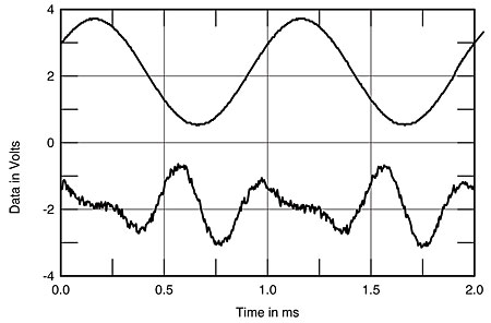
Fig.7 Moscode 401HR, 1kHz waveform at 4.4W into 8 ohms (top), 0.048% THD+N; distortion and noise waveform with fundamental notched out (bottom, not to scale).
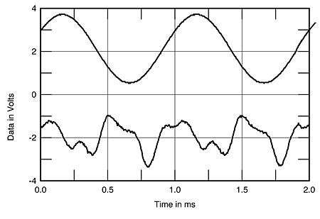
Fig.8 Moscode 401HR, 1kHz waveform at 8.3W into 4 ohms (top), 0.077% THD+N; distortion and noise waveform with fundamental notched out (bottom, not to scale).
This can also be seen in the spectrum of the amplifier's output while it drives a low-frequency tone (fig.9) and a midband tone (fig.10) at high powers into 8 and 4 ohms, respectively: At these high powers, the more subjectively annoying fifth, seventh, and ninth harmonics appear. However, intermodulation distortion, even at a level just below visible waveform clipping, is moderately low, though some high-order components are evident (fig.11).
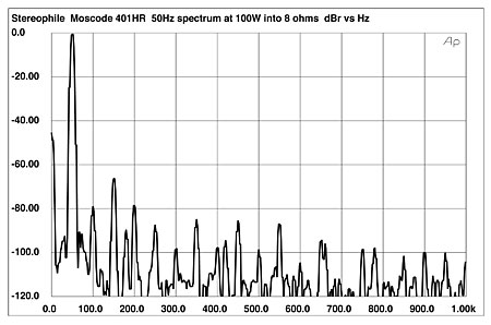
Fig.9 Moscode 401HR, spectrum of 50Hz sinewave, DC–1kHz, at 100W into 8 ohms (linear frequency scale).
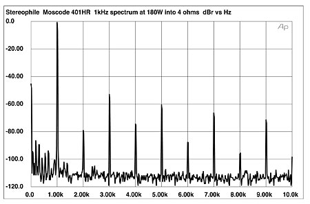
Fig.10 Moscode 401HR, spectrum of 1kHz sinewave, DC–10kHz, 180W into 4 ohms (linear frequency scale).
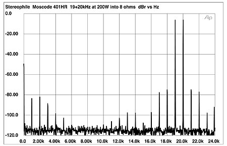
Fig.11 Moscode 401HR, HF intermodulation spectrum, DC–24kHz, 19+20kHz at 200W peak into 8 ohms (linear frequency scale).
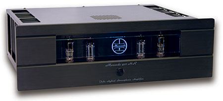
The Moscode 401HR offers pretty good measured performance, though it is clearly not happy driving loads below 4 ohms. It also looks the business, with that seductive glass front panel softly glowing blue.—John Atkinson