| Columns Retired Columns & Blogs |
The Essex Echo 1995: Electrical Signal Propagation & Cable Theory Page 2
Okay, so many of you may not have followed the details of the mathematics. Don't worry—it's really only important to appreciate the high-level procedures, namely:
Footnote 1: To those fascinated by numbers I heartily recommend two essential books: Eli Maor's e—The Story of a Number, Princeton University Press, ISBN 0-691-03390-0, 1990; and Petr Beckmann's A History of Π (Pi), St. Martin's Press, ISBN 0-312-38185-9, 1974 (Third Edition).—John Atkinson
• Commence with Maxwell's equation, from which is derived the generalized wave equation for propagation in a lossy material.
• Guess at a logical solution for a sinusoidal plane wave, knowing that Fourier analysis allows a generalization to more complicated waveforms (at least for a linear medium).
• Show that the chosen solution satisfies the wave equation, where the propagation constants α and β follow as functions of the material constants µ, ε, σ, and the angular frequency ω.
• The velocity of propagation v (in meters/s) is expressed in terms of ω and β as
v = fλ = 2Πf(λ/2Π) = ω/β
We can now classify materials into good conductors (eg, metals) and poor conductors (lossy dielectrics, or "insulators"), although this demarcation is frequency-dependent.
Poor Conductors: These are dielectric materials with very low conductivity. As σ is so small, σ is inconsequential compared with εω. Consequently, α approaches 0 and the wave experiences minimal attenuation. This condition applies to propagation in both free space and low-loss dielectrics, where the velocity of propagation can be shown to be

For "free space," the relative permeability and permittivity, µr and εr, are both equal to 1; v is equal to c, the velocity of light. This is the "fast wave" and justifies the common comment that, for audio interconnects, the velocity of propagation within the dielectric is so high that signals respond virtually instantaneously across the length of the cable. However, we must be more cautious when discussing EMC-related problems and digital interconnects communicating high-speed data where this velocity becomes a significant factor.
Table 1: Copper Electrical Properties
| σ = 5.8 x 10⁷ | (ohm-meter)–1 |
| ε = 8.855 x 10⁻¹² | farad/meter |
| µ = 4Π x 10–7 | henry/meter |
Good Conductors (such as copper): Assume ω is very much smaller than σ/ε, which for copper implies f < 1.04 x 10¹⁸Hz (see Table 1). At audio frequencies, therefore, copper is an excellent conductor, where α and β approximate to α = β = √(µωσ/2)—the values for α and β are identical for a good conductor.
The velocity of propagation in a lossy material follows from v = ω/β, whereby v = √(2ω/µσ). This is very much lower than that for a material with low conductivity.
For copper (using the material parameters in Table 1), α, β, and v are given by
α = β = 15.13 x √f and v = 0.415 x √f
Note the frequency dependence of α, β, and v—All are significant at audio frequencies!!! At 1kHz, the velocity is just 1/25 of the velocity of sound in air!
Skin Depth
Skin depth δ (delta) is defined as the distance (in meters) an electromagnetic wave propagates for its value to be attenuated by a factor of 1/e, where e is the number used as the base for natural logarithms (footnote 1). As e = 2.71828..., 1/e = 0.3679..., or –8.69dB. From the traveling wave solution, E = E0 x e–αz x sin(ωt–βz), then for z = δ, e–α = e–1, whereby

That is, the skin depth δ is the reciprocal of the attenuation constant α. However, skin depth is only a definition. You should appreciate that the fields still exists when the propagation distance z is greater than the skin depth δ, even though they are attenuated. For example, for an attenuation of just over 30dB the propagation distance is 3.5δ. Also, at z = δ, the phase (βz) of E has changed by 1 radian, or 57.3°—a far-from-negligible figure. Table 2 gives examples of calculations of skin depth and velocity against frequency for copper.
Table 2: Variation of Skin Depth & Velocity for Copper with Frequency
| Frequency | Skin depth | Velocity |
| f, Hz | Δ, mm | v, m/s |
| 50 | 9.35 | 2.93 |
| 100 | 6.61 | 4.15 |
| 1k | 2.09 | 13.12 |
| 10k | 0.66 | 41.50 |
| 20k | 0.47 | 58.69 |
The low value of velocity is directly attributable to the high value of conductivity for copper, σ = 5.8 x 10⁷ (ohm-m)–1. For comparison, for silver, σ = 6.14 x 10⁷ (ohm-m)–1. For aluminum, σ = 3.54 x 10⁷ (ohm-m)–1.
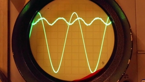
These results suggest a copper wire with a maximum diameter of between 0.5mm and 1mm is optimum if a uniform current flow across the conductor is to be maintained over the audioband. However, there are additional factors to consider: An electric field traveling within copper has a low velocity and experiences high attenuation that results in skin depths that are significant in audio interconnect design. The frequency dependence of δ (as well as α and β) should not be underestimated: the copper acts as a spatial filter where the field patterns within the conductor for a broad-band signal exhibit a complicated form (again, see fig.2). Now introduce either or both a spatially distributed non-linearity or a discontinuous conductivity as previously discussed in Hi-Fi News & Record Review (footnote 2) and the hypothesis that cables can exhibit performance defects becomes more plausible.
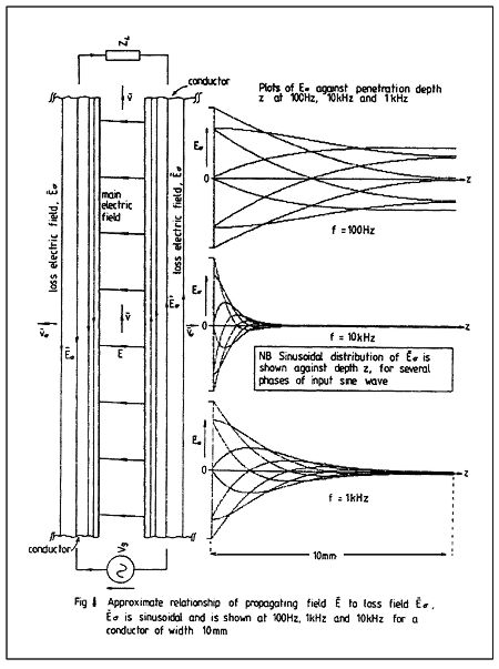
Fig.2 Approximate relationship of propagating field E-Bar to loss field B-Barσ. B-Barσ is sinusoidal and is shown at 100Hz, 1kHz, and 10kHz for a conductor of width 10mm.
Let us continue with the model development. Electromagnetic theory shows that the two conductors of a cable act as "guiding rails" for the electromagnetic energy that propagates principally through the space between the conductors, where the electrical currents in the wires are directly a result of the field boundary conditions at the dielectric/wire interface, following from Gauss's Theorem.
This may prove a more difficult conceptual step for those accustomed to lumped circuits and simple current-flow models. However, a guided-wave model is supported by electromagnetic theory irrespective of cable geometry. Only the field patterns vary, depending upon the conductor shape and their spatial relationship. This theoretical model is not new—it has been widely accepted and practiced by engineers for many years.
Footnote 1: To those fascinated by numbers I heartily recommend two essential books: Eli Maor's e—The Story of a Number, Princeton University Press, ISBN 0-691-03390-0, 1990; and Petr Beckmann's A History of Π (Pi), St. Martin's Press, ISBN 0-312-38185-9, 1974 (Third Edition).—John Atkinson
Footnote 2: Martin Colloms, "Crystal Linear and Large," HFN/RR, November 1984, Vol.29 No.11, pp.47–49.
- Log in or register to post comments
