Other circuit details: The dual-PLL scheme works only with 44.1 and 48kHz sampling frequencies. For 32kHz decoding, the CS8412 operates without benefit of the second PLL. The output driver is a Crystal 8402, the same device used in the original DTI, as well as in the UltrajitterBug and the VSP.
Looking inside the DTI Pro revealed a very compact, neat, well-thought-out design. The single board consumes the entire chassis, and the lack of point-to-point wiring simplifies assembly. The unit runs very hot—I recommend oversized feet to provide greater air circulation around the chassis.
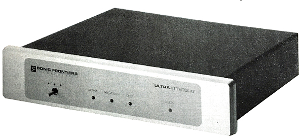
Sonic Frontiers Ultrajitterbug
The Sonic Frontiers UltrajitterBug (UJB) is the most straightforward unit of the group; its sole job is to reduce jitter. This is reflected in the unit's price, which is roughly half that of the other two units reviewed here.
The UJB is housed in a handsome, sturdy-looking chassis just 9.5" wide and a little over 2" high. The 5/16"-thick beveled faceplate holds a three-position switch which selects between inputs, and four LEDs which indicate which input has been selected, and whether the unit is locked to the source.
The rear panel holds TosLink, AES/EBU, and coaxial input jacks, AES/EBU and coaxial output jacks, and an IEC line-cord connector.
More than 80 components are housed in the 2" by 1 5/8" encapsulated module. The name UltrajitterBug itself comes from the UltraAnalog AES21 input receiver module, which replaces the Crystal CS8412 or other input receiver chip with a much more sophisticated clock-recovery circuit. The AES21 uses a Crystal CS8412 for logic decoding, along with dual discrete PLLs, for an output-clock jitter specification of 40 picoseconds. For comparison, a CS8412 has about 200ps of jitter (footnote 3). Moreover, the AES21 has a jitter-attenuation cutoff frequency of 1kHz—far lower than the CS8412's 25kHz JACF. The dual-PLL circuitry is isolated from other components in the module by a brass shield. The AES21 was designed by Dr. Rémy Fourré, whose superb article on jitter was published in the October 1993 Stereophile (Vol.16 No.10, p.80).
In addition to supplying the AES21, UltraAnalog engineers worked closely with Sonic Frontiers in designing the UJB.
The UJB has four power-supply regulation stages fed from a toroidal transformer; the master clock is supplied from its own regulation stage. Appearing at input and output are hand-wound custom transformers. These took more than a year to develop, and are reportedly critical to the UJB's performance.
A careful reading of Dr. Fourré's jitter article shows that a high-pass rolloff caused by a pulse transformer can add significantly to interface jitter. Manufacturers typically talk about interface bandwidth into hundreds of megahertz, ignoring the influence of a pulse transformer's high-pass function. These factors were considered in the UJB's design.
The UJB employs a neat trick to reduce jitter: It strips out the subcode from the S/PDIF signal. Subcode is non-audio data transmitted down the digital interface that contains information such as track number and time—when you see your CD player read the time and track information, it's getting that data from the subcode. But only CD players and transports use the subcode; digital processors don't need it.
A little earlier I mentioned that jitter is created in the interface by the music signal itself. Interestingly, the subcode also produces interface jitter at the frequency at which it's transmitted: 7.35kHz. Each subcode channel has a data rate of 7350 bits per second. This bit activity creates jitter with a frequency of 7350Hz (footnote 4). In my transport-jitter measurements presented in the November 1993 Stereophile (Vol.16 No.11, p.83), every transport measured had a peak in its jitter energy at this frequency.
This is why the UJB strips out the subcode—there's no use for it, and it only adds jitter. Note, however, that the Meridian D5000 and D6000 digital loudspeakers do rely on the S/PDIF subcode, and won't function correctly with the UJB. (The D5000 and D6000 have excellent jitter rejection anyway.)
Overall, the well-built UJB appears to be a solid piece of engineering, and its thick, beveled front panel and nice cosmetics make it the most attractive product in the group.
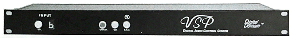
Digital Domain VSP digital audio control center
The VSP is an outgrowth of recording engineer Bob Katz's need for a box that would accept any digital format and convert it into any other digital format. His original device, the FCN-1, was a big hit in the pro world, and was nominated for Mix magazine's prestigious TEC award. The VSP expands on the FCN-1 by adding sample-rate conversion and jitter reduction.
The VSP is contained in a slim, 19"-wide chassis with removable rack-mount ears; it has six inputs and six outputs. The six inputs include three coaxial on RCA jacks, two TosLink, and one AES/EBU; outputs include three coaxial, one TosLink, one ST-Type optical, and one AES/EBU. This array easily makes the VSP the most flexible unit of the three surveyed here.
A front-panel input button scrolls through the inputs, with a numeric display indicating which input is selected. Three other illuminated buttons appear on the front panel. The Error indicator comes on when the unit isn't locked to a source; the button marked SRC (for Sample-Rate Conversion) is also marked with a J in a circle with a line through the circle—meaning "no jitter." Pressing this button engages the jitter-reduction circuit (Bob Katz calls it the "jitter-elimination" circuit).
The VSP's inside is nicely made, using the Crystal CS8412 input receiver and CS8402 output driver, along with ten TTL support chips. A bank of relays switches input and output signals. Incoming AC is filtered before being fed to the power transformer.
The heart of the VSP is the Analog Devices AD1890 sample-rate converter. Designed by Robert Adams and intended for professional applications, this chip accepts digital audio data at any input sampling frequency and outputs those data at a specified sampling frequency. The AD1890 is actually called an "asynchronous" sample-rate converter, because the input and output clocks are completely independent. Consequently, the input clock can be highly jittered, yet the output clock remains clean. It is this aspect of the AD1890 that the VSP exploits to accomplish jitter reduction. Any jitter present in its output will only be that of its output word-clock generator.
The data representing the audio signal passing through the AD1890 undergo significant manipulation, however. To perform its rate conversion, the AD1890 has a high-oversampling digital filter that creates a large number of new sample points between the incoming audio samples. A resampling decimation filter then selects from the very-high-rate samples those that fit the desired output sampling rate. Put another way, the AD1890 creates lots of new samples, then throws out those it doesn't need. Consequently, the data words that come out are not the same data as those that went in.
If the oversampling ratio were infinite, this process would be completely transparent. The output samples would describe exactly the same waveform as the input words. But it is possible, given that the 1890's oversampling ratio is finite, that there would occasionally not be a sample present at the time instant dictated by the output data rate, which would result in a small amplitude error. Jitter itself can be thought of as an amplitude error—a time difference in which the reconstructed sample creates an amplitude error in the final analog waveform. The right amplitude at the wrong time is the wrong amplitude. Conversely, the AD1890 outputs samples at precisely the right time, but it is possible that their amplitude will have been slightly altered by the oversampling and decimation process. In other words, the right samples go in at the wrong time, and possibly emerge as very slightly wrong samples at the right time.
Proponents of the AD1890 argue that the device's interpolation ratio is so high that any sample errors are minuscule, of the order of the existing quantization noise. Nonetheless, it should be noted that because the AD1890 rewrites the data words representing the audio signal, many engineers have expressed reservations about using the AD1890 for jitter reduction (footnote 5).
Moreover, the AD1890 won't be compatible with High Definition Compatible Digital (HDCD). That process buries a control code in the digital samples' LSBs. Any change in the data will destroy this control code, which instructs the HDCD decoder how to process the audio signal.
Listening to the DTI Pro
Sharp-eyed readers may have noticed that I've been using the DTI Pro in my system nearly continuously since the Genesis II.5 loudspeakers were delivered; Arnie Nudell and Paul McGowan of Genesis brought an early DTI Pro sample with the II.5s and insisted I listen to it.
Because the DTI Pro became part of the playback system when the II.5s were set up, I didn't realize how much the DTI Pro was contributing to the absolutely magical sound I was getting from the system. When I removed the DTI Pro, the system's sound was still excellent, but lacked the transparency, some of the huge sense of space, timbral rightness, and musicality I'd become accustomed to.
The DTI Pro's effects must be heard to be believed. The first thing that struck me about it was the huge amount of space, air, depth, and soundstage layering it resolved—the presentation became bigger, deeper, wider, more focused. The sense of hall reverberation surrounding instruments was greatly enhanced, and instruments toward the rear of the soundstage were enveloped in air, more vivid and alive, and set farther back.
Further enhancing the DTI Pro's spectacular effect on the sense of air and space was the way it stripped away an opacity in the soundstage—the feeling of transparency, immediacy, and ability to hear deep into the soundstage was astounding. The DTI Pro's startling, crystal-clear transparency gave music a greater immediacy and vitality, yet the presentation was never forward or pushy. I'm not talking about a marginal increase in these factors, but a wholesale improvement in the music's spatial presentation. In fact, the DTI Pro made the $750 Adcom GDA-600 sound like a $4000 processor.
The next biggest area of improvement was the DTI Pro's huge increase in resolution of musical detail. Removing the DTI Pro for a few weeks, then returning it to the system, revealed just how much more information the unit allowed the digital processors to resolve. The music was infused with fine structure and inner detail, making the presentation without the DTI Pro seem coarse and blunt. When combined with the heightened soundstage transparency, the DTI Pro's increased ability to portray detail was a revelation. Listen, for example, to the percussion in the back of the ensemble on Frank Zappa's The Yellow Shark (Barking Pumpkin R2-71600). The instruments took on a much more real and separate identity, rather than sounding like just another sound.
Footnote 3: UltraAnalog measures the jitter of all incoming CS8412s, and has discovered that their intrinsic jitter varies from a low of 140ps to a high of more than 400ps. Crystal specifies the CS8412 as typically 200ps, but doesn't guarantee the device's jitter performance. If you've ever heard sample-to-sample variability in a model of digital processor, the CS8412's varying jitter performance may be the culprit.
Footnote 4: If you want to know why, read Rémy Fourré's feature article in the October '93 Stereophile, and Malcolm Hawksford's seminal paper, "Is the AES/EBU–S/PDIF Interface Flawed?," presented at the 1992 Audio Engineering Society Convention in San Francisco. These two pieces are required reading for all digital audio designers.
Footnote 5: See, for example, the letter from David Smith of Sony Classical in the September '94 Stereophile (Vol.17 No.9, pp.12–15).