Sidebar 3: Measurements
I measured the Jadis JA200 Mk.II with my Audio Precision SYS2722 system (see the January 2008 As We See It"). One point to note is that with 10 KT150 tubes packed closely together on the amplifier chassis, the JA200 Mk.II gets very hot. After a couple of hours, the temperature of the top panel by the output transformer was 169°F (76.2°C)!
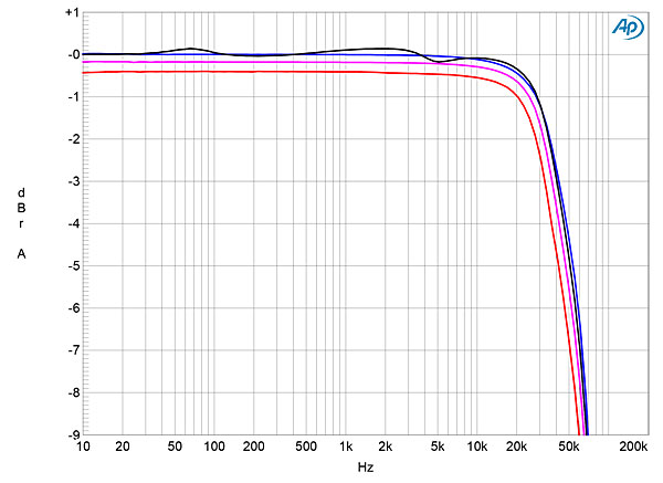
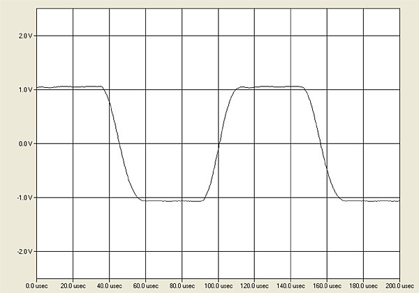
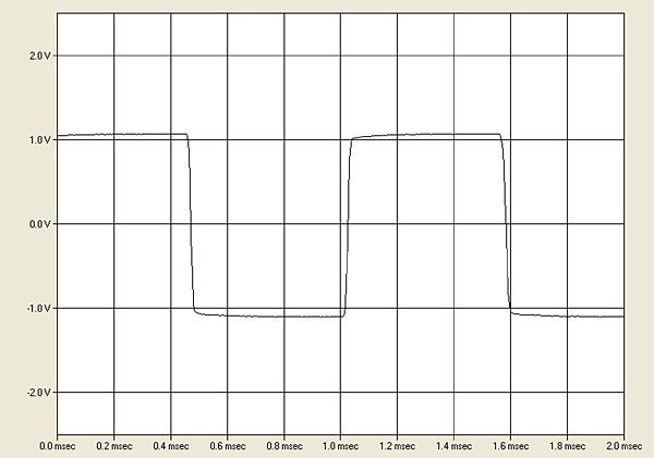
The voltage gain into 8 ohms was 30.5dB, and the Jadis preserved absolute polarity (ie, was non-inverting). The input impedance was very high, at >500k ohms at low and middle frequencies, and still 300k ohms at the top of the audioband. The output impedance (including 6' of speaker cable) was very low for a transformer-coupled tube amplifier, at 0.18 ohm at 20Hz and 1kHz, and 0.14 ohm at 20kHz. As a result, the modification of the amplifier's frequency response with our standard simulated loudspeaker was small, at less than ±0.2dB (fig.1, gray trace). There is no trace of any ultrasonic resonance in this graph, as there had been with the original version of the JA200 (footnote 1), and there was no overshoot or ringing with the amplifier's reproduction of a 10kHz squarewave (fig.2), though the lengthened risetimes correlate with the reduction in output at ultrasonic frequencies seen in fig.1. A 1kHz squarewave (fig.3) was reproduced with flat tops and bottoms, which implies an excellent output transformer that makes possible an extended low-frequency response.
Footnote 1: See figs. 1–3 here.
Fig.1 Jadis JA200 Mk.II, frequency response at 2.83V into: simulated loudspeaker load (gray), 8 ohms (blue), 4 ohms (magenta), 2 ohms (red) (0.5dB/vertical div.).
Fig.2 Jadis JA200 Mk.II, small-signal, 10kHz squarewave into 8 ohms.
Fig.3 Jadis JA200 Mk.II, small-signal, 1kHz squarewave into 8 ohms.
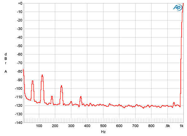
The JA200 Mk.II's unweighted, wideband signal/noise ratio, ref. 1W into 8 ohms, was an excellent 80.3dB, improving to 92.4dB when A-weighted. AC-supply harmonics were relatively low in level (fig.4). This is a quiet amplifier, with no evidence in its noise performance that it uses tubes.
Fig.4 Jadis JA200 Mk.II, spectrum of 1kHz sinewave, DC–1kHz, at 1W into 8 ohms (linear frequency scale).
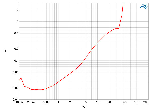
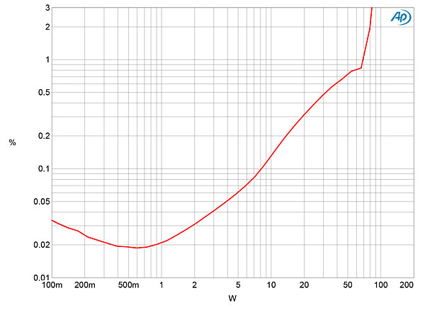
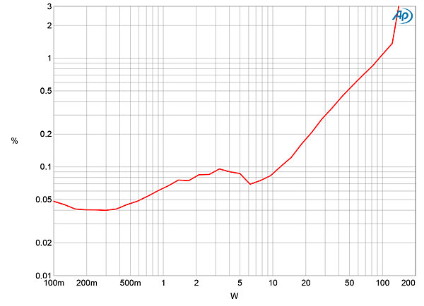
We define clipping as when the percentage of THD+noise in an amplifier's output reaches 1%. While Jadis specifies the JA200 Mk.II's output power as being 160 or 170W, when I plotted how the THD+N percentage varied with power into 8 ohms (fig.5), I measured just 39W (15.9dBW) at 1% THD+N, a shortfall of 6dB. Even at 3% THD+N the power was only 0.5dB higher, at 44W. When I repeated the measurement into 4 ohms (fig.6), the Jadis delivered 70W at 1% THD+N and 84W at 3%. The amplifier began to approach its specified power output only into 2 ohms (fig.7), where the 1% power was 99.7W and the 3% power 140W.
Fig.5 Jadis JA200 Mk.II, distortion (%) vs 1kHz continuous output power into 8 ohms.
Fig.6 Jadis JA200 Mk.II, distortion (%) vs 1kHz continuous output power into 4 ohms.
Fig.7 Jadis JA200 Mk.II, distortion (%) vs 1kHz continuous output power into 2 ohms.
I was puzzled by these results, as they suggest that the internal strapping of the Jadis's output transformer had been set up not for "4–8 ohms," as the distributor's representative had assured Jason Serinus, but for a lower impedance. Indeed, when I removed the JA200 Mk.II's bottom plate and compared the connections with those printed in the manual, it became apparent that this sample of the amplifier had been optimized for a 1 ohm load. I don't have a 1 ohm test load, but I suspect that, as set up before it was sent to us for review, the JA200 Mk.II will deliver its specified power into 1 ohm. And as Jason's Wilson speakers have a minimum impedance of just under 2 ohms at 86Hz, with a demanding combination of 3.6 ohms and –43° phase angle at 54Hz, having the Jadis amplifier strapped for 1 ohm operation was probably a good idea.
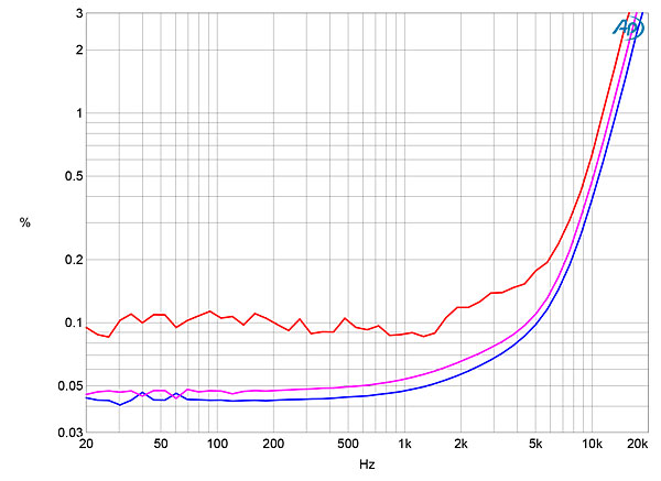
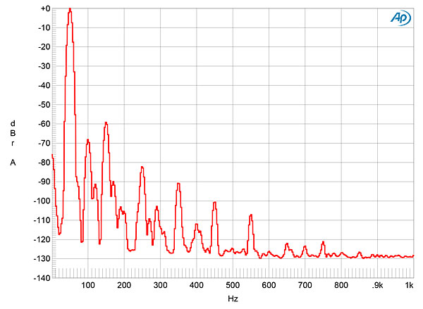
Fig.8 plots the Jadis's THD+N percentage against frequency at 4V, which is equivalent to 2W into 8 ohms, 4W into 4 ohms, and 8W into 2 ohms. The THD is very low at low and middle frequencies into 8 and 4 ohms, but is higher into 2 ohms. However, note the big rise in THD in the treble, over 0.1% above 5kHz and reaching 3% just below 20kHz. The distortion signature primarily comprises the relatively benign third harmonic (fig.9), though some second and fifth harmonics are also present (fig.10).
Fig.8 Jadis JA200 Mk.II, THD+N (%) vs frequency at 4V into: 8 ohms (blue), 4 ohms (magenta), 2 ohms (red).
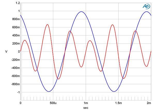
Fig.9 Jadis JA200 Mk.II, 1kHz waveform at 4W into 8 ohms, 0.085% THD+N (blue); distortion and noise waveform with fundamental notched out (red, not to scale).
Fig.10 Jadis JA200 Mk.II, spectrum of 50Hz sinewave, DC–1kHz, at 10W into 4 ohms (linear frequency scale).
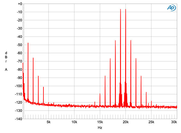
It was only when I examined the JA200 Mk.II's intermodulation distortion that I ran into trouble. My intermodulation test signal comprises two tones, equal in level, at 19 and 20kHz. With the Jadis's significant decrease in linearity at the top of the audioband, the intermodulation products are rising above 0.3% at levels as low as 2W into 4 ohms (fig.11). At 10W into 4 ohms (not shown), the difference product at 1kHz lay at –34dB (2%), and the higher-order products at 18 and 21kHz were each close to 10% in level. To be fair, the Mk.II JA200 is actually no worse in this respect than the original version we reviewed in 1993. Fortunately, music rarely has high levels of energy at the top of the audioband, so this behavior might go unnoticed much of the time. But what was acceptable almost a quarter-century ago is no longer acceptable today, I feel.
Fig.11 Jadis JA200 Mk.II, HF intermodulation spectrum, DC–30kHz, 19+20kHz at 2W peak into 4 ohms (linear frequency scale).
When I removed the Jadis JA200 Mk.II's bottom plate to check its output-transformer wiring, I was impressed by the high standard of construction: hardwired throughout, with meticulous layout of the circuit components, and an output transformer of obviously superb quality. The amplifier's measured performance is also excellent in most ways. But I just can't get away from that poor linearity at high frequencies.—John Atkinson
Footnote 1: See figs. 1–3 here.