Bryston BP-173 preamplifier: phono & DAC module measurements, July 2019 (Vol.42 No.7):
After Larry Greenhill had finished auditioning the updated sample of Bryston's BP-173 preamplifier—see his Follow-Up review in the June issue—he shipped it to me so I could measure its new phono and D/A stages with my Audio Precision SYS2722 system (see the January 2008 "As We See It").
Looking first at the phono stage: I floated the preamp's outputs and ran a separate ground connection to the analyzer, which gave the lowest level of noise. With the volume control at its maximum setting, the voltage gain at 1kHz into 100k ohms measured 59.3dB from the balanced line outputs, 53.3dB from the unbalanced line outputs, and 41.6dB from the tape outputs. As the line stage applies a maximum gain of 17.5dB from the balanced outputs and 11.6dB from the unbalanced outputs, the maximum phono-stage gains are appropriate for moving-magnet cartridges. All three outputs inverted absolute polarity with phono input signals. The phono input impedance was close to 47k ohms at low and middle frequencies, dropping slightly to 39k ohms at 20kHz, both impedances also appropriate for MM cartridges.
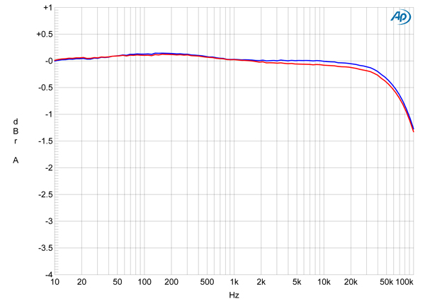
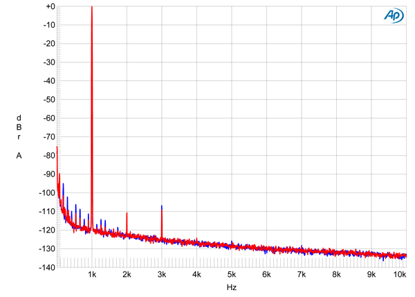
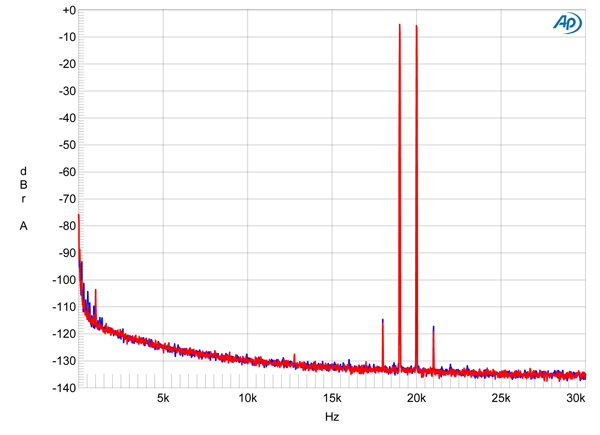
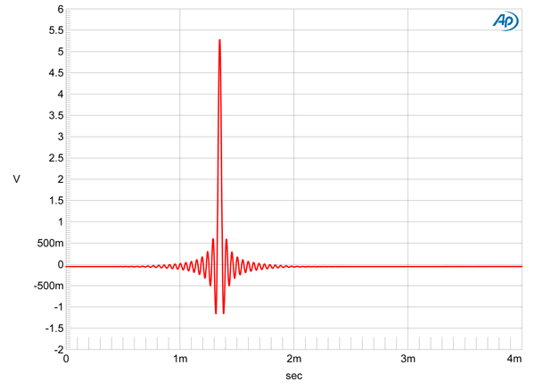
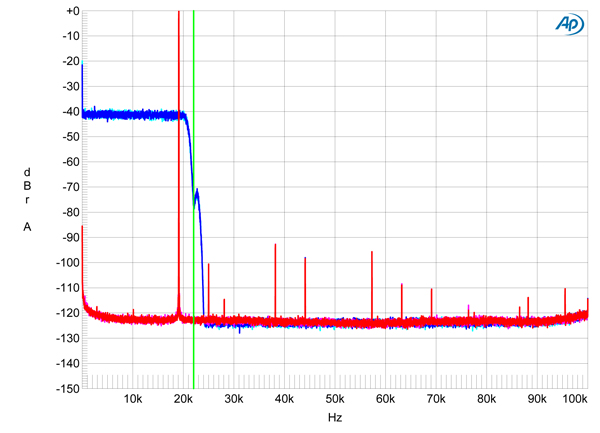
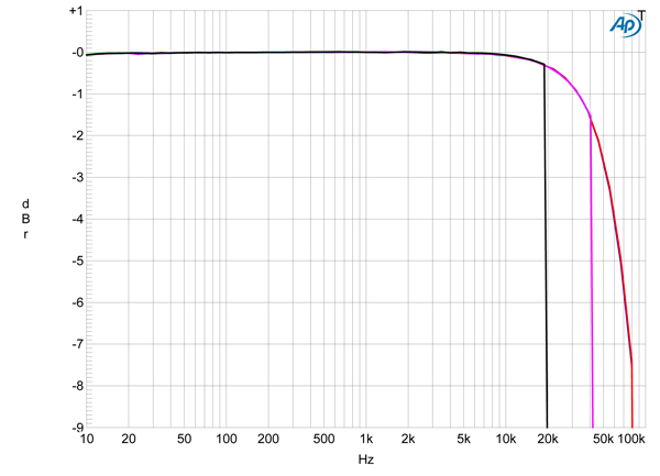
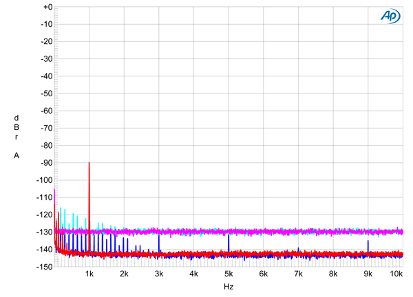
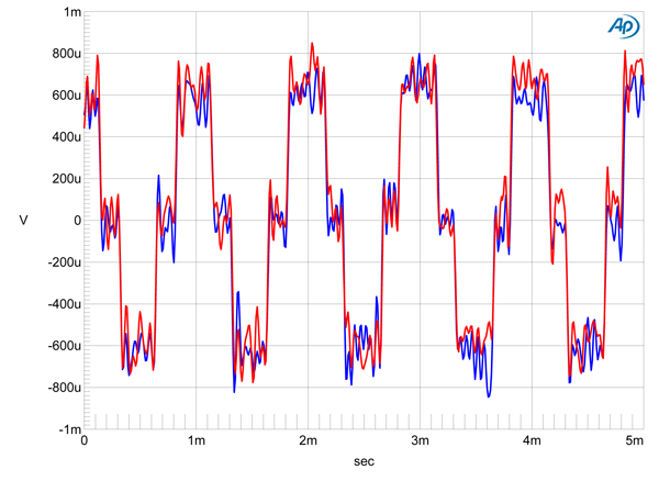
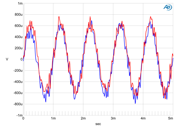
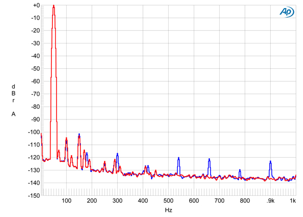
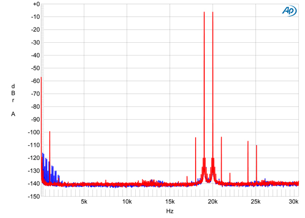
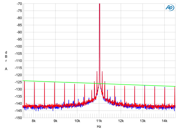
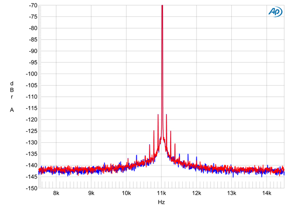
Fig.1 Bryston BP-173, phono input, response with RIAA correction (left channel blue, right red) (1dB/vertical div.).
As claimed by Bryston, the phono-stage RIAA error was extraordinarily low (fig.1), and the output didn't roll off until well above the audioband, reaching –1dB at 90kHz. Channel separation was excellent, at >70dB in both directions. With the phono inputs shorted to ground and the volume control set to its maximum, the wideband, unweighted signal/noise ratio (ref. a 1kHz input signal at 5mV) measured 73dB in the left channel and 74.5dB in the right, both results superb. An A-weighting filter increased the ratios to >81dB in both channels. This is a very quiet phono stage.
Fig.2 Bryston BP-173, phono input, spectrum of 1kHz sinewave, DC–1kHz, at 20mV input level (linear frequency scale).
Fig.3 Bryston BP-173, phono input, HF intermodulation spectrum, DC–30kHz, 19+20kHz at 20mV peak input level (linear frequency scale).
Phono-input overload margins were very good, at 16dB from 20Hz to 20kHz, and both harmonic distortion (fig.2) and intermodulation distortion (fig.3) were extremely low in level, even at input levels 12dB higher than usual.
Turning to the Bryston's digital input stage, the coaxial S/PDIF input locked to datastreams with all sample rates up to 192kHz, the optical input to datastreams up to 96kHz. Both digital inputs preserved absolute polarity. With the volume control at its maximum setting, a 1kHz digital signal at 0dBFS resulted in a balanced output level of 15.3V and an unbalanced output level of 7.62V, which suggest that the digital inputs have too much gain. I continued testing the digital inputs from the BP-173's balanced outputs.
Fig.4 Bryston BP-173, digital input, impulse response (one sample at 0dBFS, 44.1kHz sampling, 4ms time window).
Fig.5 Bryston BP-173, digital input, wideband spectrum of white noise at –4dBFS (left channel blue, right cyan) and 19.1kHz tone at 0dBFS (left red, right magenta), with data sampled at 44.1kHz (20dB/vertical div.).
The Bryston's impulse response with 44.1kHz data (fig.4) indicates that its reconstruction filter is a conventional linear-phase type, with ringing before and after the single sample at 0dBFS. With 44.1kHz-sampled white noise (fig.5, blue and cyan traces), the Bryston's response rolled off rapidly above the audioband, reaching full stop-band suppression at 24kHz, but with a null at the Nyquist frequency of 22.05kHz (vertical green line). An aliased image at 25kHz of a full-scale tone at 19.1kHz (red and magenta traces) is suppressed by 100dB. The distortion harmonics of the 19.1kHz tone are visible above the ultrasonic noise floor but are very low in level. The highest-level harmonic, the second, lies at an extremely low –93dB (0.002%).
Fig.6 Bryston BP-173, digital input, frequency response at –12dBFS into 100k ohms with data sampled at: 44.1kHz (left channel green, right gray), 96kHz (left cyan, right magenta), 192kHz (left blue, right red) (1dB/vertical div.).
When I examined the BP-173's digital frequency response with S/PDIF data at 44.1, 96, and 192kHz, the response followed the same basic shape at each sample rate, with a rolloff that reached just –0.3dB at 20kHz and a sharp rolloff just below each Nyquist frequency (fig.6). Channel separation via the digital input was >107dB below 2kHz, this falling to a still-excellent 90dB at the top of the audioband due to capacitive coupling between the channels.
Fig.7 Bryston BP-173, digital input, spectrum with noise and spuriae of dithered 1kHz tone at –90dBFS with: 16-bit data (left channel cyan, right magenta), 24-bit data (left blue, right red) (20dB/vertical div.).
When I increased the bit depth from 16 to 24 with a dithered 1kHz tone at –90dBFS (fig.7), the noise floor dropped by about 15dB, meaning that the Bryston offers between 18 and 19 bits' worth of resolution.
Fig.8 Bryston BP-173, digital input, waveform of undithered 1kHz sinewave at –90.31dBFS, 16-bit TosLink data (left channel blue, right red).
Fig.9 Bryston BP-173, digital input, waveform of undithered 1kHz sinewave at –90.31dBFS, 16-bit TosLink data (left channel blue, right red).
With undithered data representing a tone at exactly –90.31dBFS, the three DC voltage levels described by the data were well resolved and the waveform was perfectly symmetrical (fig.8). With 24-bit undithered data, the result was a clean sinewave (fig.9)
Fig.10 Bryston BP-173, digital input, spectrum of 50Hz sinewave, DC–1kHz, at 0dBFS into 600 ohms (left channel blue, right red; linear frequency scale).
Fig.11 Bryston BP-173, digital input, HF intermodulation spectrum, DC–30kHz, 19+20kHz at 0dBFS into 100k ohms, 44.1kHz data (left channel blue, right red; linear frequency scale).
As with the Bryston's phono stage, harmonic (fig.10) and intermodulation (fig.11) distortion via its digital inputs were very low. When I tested the digital inputs' rejection of word-clock jitter with 16-bit J-Test data, the odd-order harmonics of the LSB-level, low-frequency squarewave were all at the correct levels (fig.12, sloping green line), though sidebands at the power-supply–related frequencies of ±120 and ±240Hz are evident. This graph was taken with optical data; the BP-173 behaved identically with coaxial data and 24-bit data (fig.13).
Fig.12 Bryston BP-173, digital input, high-resolution jitter spectrum of analog output signal, 11.025kHz at –6dBFS, sampled at 44.1kHz with LSB toggled at 229Hz: 16-bit optical S/PDIF data (left channel blue, right red). Center frequency of trace, 11.025kHz; frequency range, ±3.5kHz.
Fig.13 Bryston BP-173, digital input, high-resolution jitter spectrum of analog output signal, 11.025kHz at –6dBFS, sampled at 44.1kHz with LSB toggled at 229Hz: 24-bit coaxial S/PDIF data (left channel blue, right red). Center frequency of trace, 11.025kHz; frequency range, ±3.5kHz.
The Bryston BP-173 offered superb measured performance as a line preamplifier. Its optional phono and digital inputs are equally excellent.—John Atkinson


