Sidebar 3: Measurements
I performed a full set of measurements on the Air Tight ATM-1S, using my Audio Precision SYS2722 system (see www.ap.com and the January 2008 "As We See It). Before I did any testing, I let the amplifier run for an hour with a 1kHz tone at 1Wpc into 8 ohms, then turned off the input and checked that the bias current for each of its four output tubes had been correctly set. I used the rear-panel inputs for the testing, and repeated some tests using the front-panel input jacks to see if there were any differences. There weren't.
As Art Dudley surmised, the ATM-1S preserved absolute polarity (ie, was non-inverting). The input impedance was high, varying from 65k ohms at 20Hz to 58k ohms at 20kHz. The two channels differed in their voltage gain at 1kHz into 8 ohms, the left measuring 27.3dB, the right 29.6dB; the difference of 2.3dB was equivalent to two dots on the level controls' peripheral scales. For all subsequent testing, I reduced the gain of the right channel with its level control to match the left. When I asked AD if he'd noticed any channel imbalance in his auditioning, he said that he did indeed have to keep the left-channel gain higher than the right—but elaborated that, in his room, he finds he must always do this so that mono signals will sound centered. "Perhaps I had to do that to a greater degree with the Air Tight than with other amps," he added; but if so, "I failed to notice that difference."
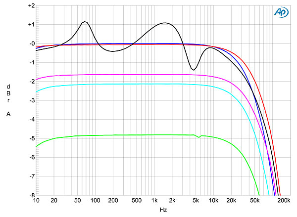
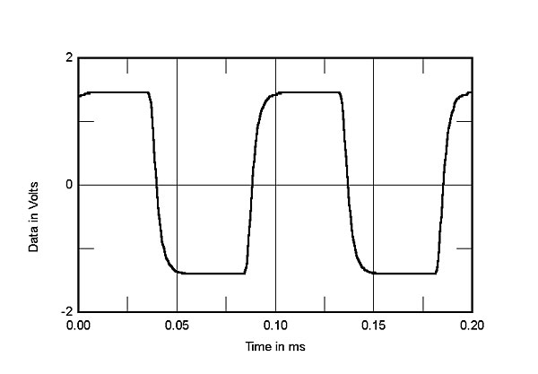
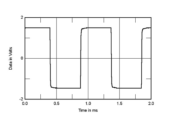
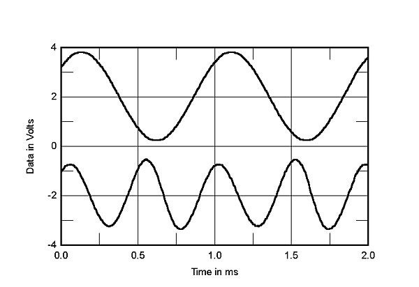
As is usual with a transformer-coupled amplifier using a push-pull pair of EL34 or 6CA7 tubes, the Air Tight's output impedance was high, ranging from 3.6 ohms at 20Hz to 3.3 ohms at 20kHz. This suggests that the single output-transformer tap is optimized for a 4 ohm load, but it results in response variations of ±1.1dB with the magazine's standard simulated loudspeaker (fig.1, gray trace). This graph also shows that, comparing their respective levels into 4 and 8 ohms, the left channel (cyan trace) drops more than the right (magenta), which suggests that the right channel's output impedance is not as high as the left channel's. The ATM-1S's ultrasonic output drops by 3dB at 60kHz (left) and 70kHz (right)—respectable performance for a tubed design. As a result, its 10kHz squarewave response was excellent, with short risetimes (fig.2), and the flat tops in the amplifier's reproduction of a 1kHz squarewave suggest extended low-frequency response (fig.3). Both squarewaves are free from overshoot and ringing, which means the ATM-1S is both stable and features well-designed output transformers.
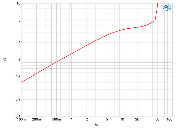
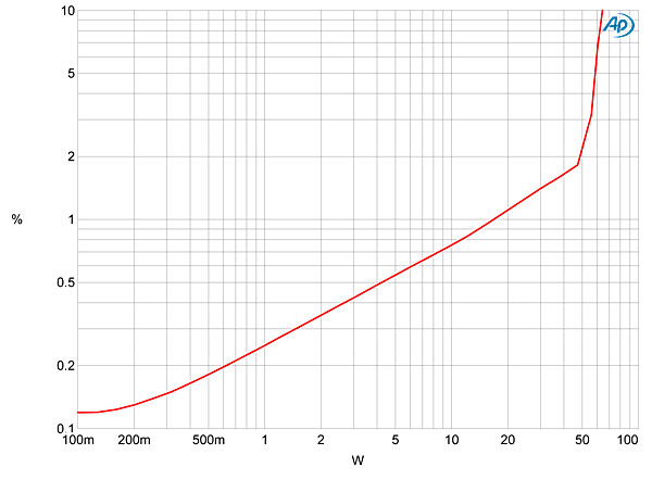
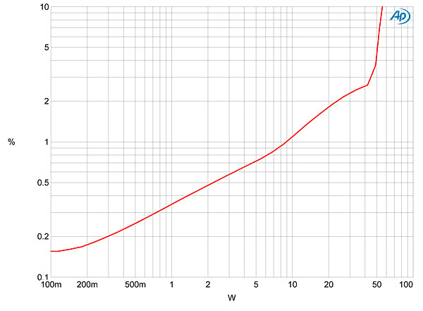
 When I measured how the left channel's percentage of distortion plus noise varied with output power into 8 ohms, the resultant graph (fig.5) suggested that there was something wrong. Not only was the distortion 0.6% at 100mW, it rose to 1% at 650mW and to 4% at 30W. Repeating the test with the right channel gave a very different picture (fig.6): The THD at 100mW was now 0.15%, and the slow rise in the distortion percentage with increasing power suggests that the ATM-1S's circuit uses only a small amount of negative feedback. We usually define clipping as when the THD+noise reaches 1%—which, in the ATM-1S's right channel, occurs at 9W (6.5dBW). However, looking at the waveform on an oscilloscope reveals that the signal isn't clipped at this power; true waveform clipping actually occurs just above 40W, with the THD+N reaching 3% at 46W (16.6dBW), 1dB higher than the specified 36W (15.6dBW). Into 4 ohms (fig.7), the right channel reaches 1% THD+N at 17W (15.3dB) and 3% at 52W (14.2dBW).
 I suspect that the much better behavior of its right channel is more likely to be representative of the Air Tight ATM-1S's intrinsic performance than is the left channel's. As AD mentioned, this was a much-traveled sample, and it's possible that a tube had been slowly going bad during the time we had the amplifier in for review. After writing this sidebar, I tried to repeat some of the measurements with the output tubes swapped from side to side. However, the ATM-1S buzzed loudly when it was turned on, suggesting that something inside was now broken (footnote 1).—John Atkinson
Footnote 1: When the amplifier was returned to the distributor, it turned out that an output tube in the left channel had indeed failed. —John Atkinson
Fig.1 Air Tight ATM-1S, frequency response at 2.83V into: simulated loudspeaker load (gray), 8 ohms (left channel blue, right red), 4 ohms (left cyan, right magenta), 2 ohms (green) (1dB/vertical div.).
Fig.2 Air Tight ATM-1S, small-signal 10kHz squarewave into 8 ohms.
Fig.3 Air Tight ATM-1S, small-signal 1kHz squarewave into 8 ohms.
Channel separation (not shown) was asymmetrical, with the L–R crosstalk at 1kHz being a high 93dB but the R–L crosstalk 72dB. The unweighted, wideband signal/noise ratio was also different in the two channels, measuring 75.7dB ref. 2.83V into 8 ohms, left, and 69.4dB, right, both measured with the inputs shorted to ground. Switching an A-weighting filter into circuit improved both ratios, to 82.7dB left and 80.7dB right. Spectral analysis of the Air Tight's noise floor while it drove a 1kHz tone at 1W into 8 ohms (fig.4) revealed that the right channel had more 120 and 240Hz components than the left, these frequencies related to the full-wave–rectified power supply. In both channels, however, were spuriae at 60 and 180Hz, which will be due to magnetic interference from the AC transformer.
Fig.4 Air Tight ATM-1S, spectrum of 1kHz sinewave, DC–1kHz, at 1W into 8 ohms (left channel blue, right red; linear frequency scale).
Fig.5 Air Tight ATM-1S, left channel, distortion (%) vs 1kHz continuous output power into 8 ohms.
Fig.6 Air Tight ATM-1S, right channel, distortion (%) vs 1kHz continuous output power into 8 ohms.
Fig.7 Air Tight ATM-1S, right channel, distortion (%) vs 1kHz continuous output power into 4 ohms.
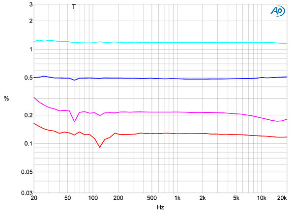
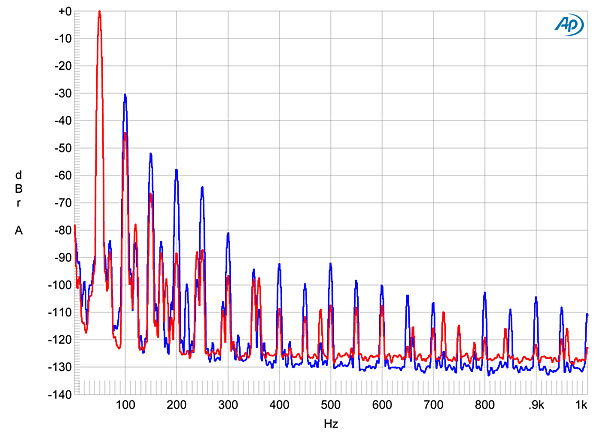
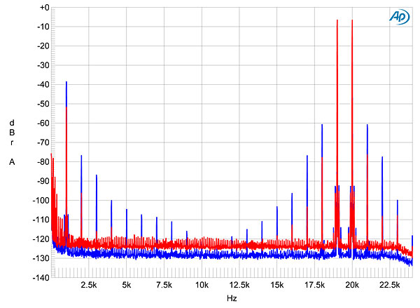
The dramatically higher level of distortion in the left channel can be seen in fig.8, which plots the THD+N percentage at 1.1V into 8 ohms (blue and red traces) and 4 ohms (cyan, magenta). Fortunately, the distortion residual in both channels is heavily second-harmonic in nature (fig.9), which will be subjectively innocuous, provided it is not accompanied by significant intermodulation distortion. The spectral analysis in fig.10, taken at 5Wpc into 8 ohms, shows the drastically higher levels of second and higher harmonics in the left channel (blue trace). While the level of the difference product at 1kHz as the amplifier drives an equal mix of 19 and 20kHz tones into 8 ohms at a peak signal level of 5Wpc (fig.11) reaches –39dB (1.1%) in the left channel and –53dB (0.2%) in the right, the higher-order products all remain at or below –60dB (0.1%), even in the left channel.
Fig.8 Air Tight ATM-1S, THD+N (%) vs frequency at 1V into: 8 ohms (left channel blue, right red), 4 ohms (left cyan, right magenta).
Fig.9 Air Tight ATM-1S, left channel, 1kHz waveform at 500mW into 8 ohms, 0.6% THD+N (top); distortion and noise waveform with fundamental notched out (bottom, not to scale).
Fig.10 Air Tight ATM-1S, spectrum of 50Hz sinewave, DC–1kHz, at 5W into 8 ohms (linear frequency scale).
Fig.11 Air Tight ATM-1S, HF intermodulation spectrum, DC–30kHz, 19+20kHz at 5W peak into 8 ohms (linear frequency scale).
Footnote 1: When the amplifier was returned to the distributor, it turned out that an output tube in the left channel had indeed failed. —John Atkinson


