Sidebar 2: Measurements
The Adcom GDA-700 had a maximum output level of 4.44V from the balanced outputs and 2.1V from the single-ended jacks. The output impedance was a low 78 ohms (unbalanced) and 156 ohms (balanced). DC levels were low (2.9mV left channel, 1.3mV right channel), and the unit doesn't invert absolute polarity. The GDA-700 also had no trouble decoding 32kHz and 48kHz sampling frequencies.
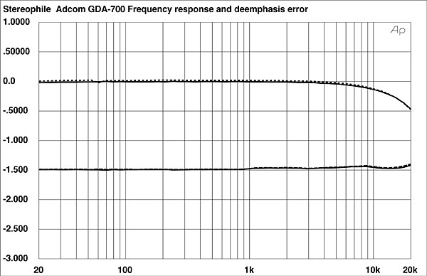
Fig.1 shows the GDA-700's flat frequency response and perfect de-emphasis tracking. The rolloff of 0.5dB at 20kHz is slightly steeper than in many processors, but should be inaudible. The perfect de-emphasis tracking is the result of the digital-domain de-emphasis performed in the PMD100 digital filter and HDCD decoder.
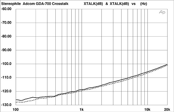
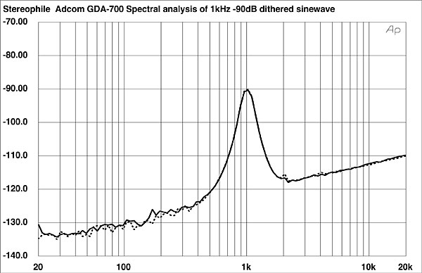
 The GDA-700's crosstalk performance (fig.2) was exceptional, with nearly 120dB of channel separation at 1kHz, and greater than 100dB separation at 20kHz. Performing a spectral analysis on the GDA-700's output when decoding a 1kHz, –90dB dithered 20-bit sinewave (fig.3) revealed exceptionally low noise and complete lack of power-supply noise in the audio output. (Power-supply noise is seen as peaks in the trace at 60Hz and/or its harmonics). The GDA-700's plot is completely clean (footnote 1). Note the expanded scale (down to –140dB) needed to show the extremely low noise of this design. The slight trace of second-harmonic distortion (the small peak at 2kHz) is commonly seen in 20-bit processors when driven with 20-bit input words, I have found.
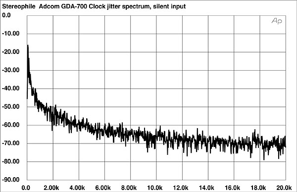
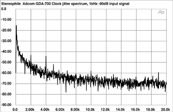
 With an input signal of all zeros, the jitter spectrum was perfectly clean (fig.11), and the RMS level was 35ps. The RMS level rose to 90ps With a 1kHz, –90dB sinewave input, and the spectrum shows some periodic components related to the test-signal frequency (fig.12).
 Overall, the GDA-700 had superlative technical performance. The high channel separation, terrific linearity, excellent noise modulation, and good jitter performance are impressive for a $1000 processor.—Robert Harley
Footnote 1: Although the AC power-line frequency from a wall outlet is 60Hz, we most often see power-supply noise at 120Hz. The power supply's job is to convert the 60Hz Alternating Current (AC) from the wall outlet into Direct Current (DC) that supplies the component's circuits. Converting AC to DC is called "rectification." An arrangement of diodes called a "full-wave bridge rectifier" essentially inverts one phase of the AC line, the result being 120 pulses per second of the same polarity. Leakage of the rectified 120Hz noise into the analog signal path pollutes the audio signal in some audio components.—Robert Harley
Fig.1 Adcom GDA-700, frequency response (top) and de-emphasis error (bottom) (right channel dashed, 0.5dB/vertical div.).
Fig.2 Adcom GDA-700, crosstalk (R–L channel dashed, 10dB/vertical div.).
Fig.3 Adcom GDA-700, spectrum of dithered 1kHz tone at –90.31dBFS, with noise and spuriae (20-bit data, 1/3-octave analysis, right channel dashed).
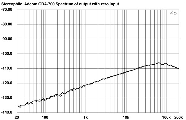
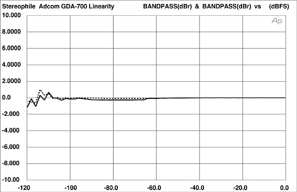
The same measurement, but with an input of all zeros and a 200kHz bandwidth (fig.4), again shows the GDA-700's low noise and good out-of-band behavior. Moving next to the GDA-700's linearity (fig.5), we can see the unit's superb linearity and lack of noise (the trace doesn't skyrocket below –100dB). The left channel has a minuscule (a small fraction of a dB) negative error starting at –65dB, but this is so small you may not be able to see it on the reproduced graph. The GDA-700's DACs are virtually perfect to below –115dB, implying nearly true 20-bit performance.
Fig.4 Adcom GDA-700, spectrum of digital silence (20-bit data, 1/3-octave analysis, right channel dashed).
Fig.5 Adcom GDA-700, departure from linearity (right channel dashed, 2dB/vertical div.).
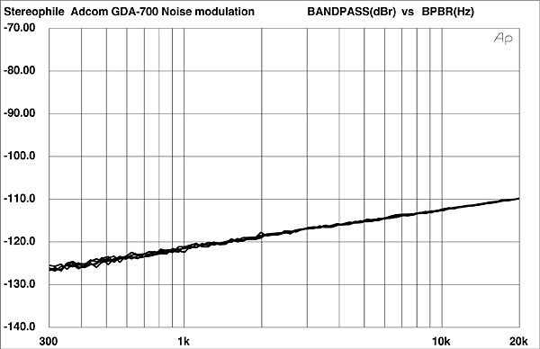
The GDA-700 also performed well on the noise-modulation test, shown in fig.6. The traces are so close together they appear almost as a single line. This indicates that the GDA-700's noise floor doesn't shift in level or change its spectral balance as the input signal amplitude changes. This is among the best noise-modulation plots I've seen.
Fig.6 Adcom GDA-700, noise modulation, –60 to –100dBFS (10dB/vertical div.).
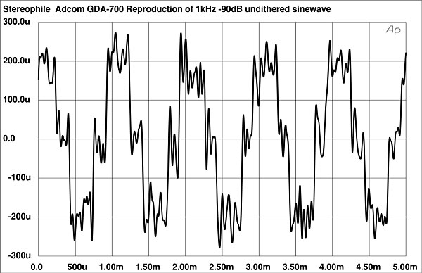
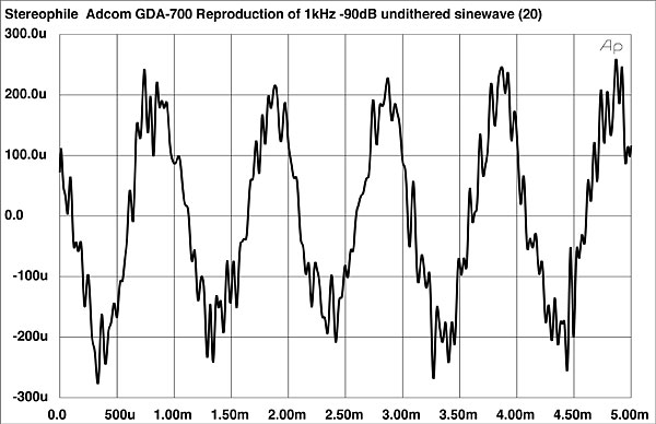
Fig.7 is the GDA-700's reproduction of a 1kHz, –90dB undithered sinewave with 16-bit resolution. The step sizes are uniform, and the waveshape is good. Fig.8 is the same waveform with a 20-bit input precision.
Fig.7 Adcom GDA-700, waveform of undithered 1kHz sinewave at –90.31dBFS (16-bit data).
Fig.8 Adcom GDA-700, waveform of undithered 1kHz sinewave at –90.31dBFS (20-bit data).
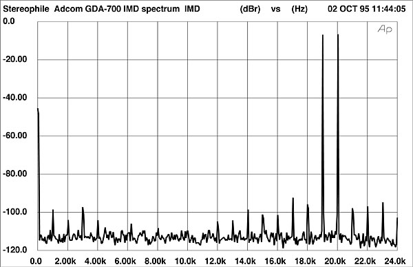
An FFT-derived spectral analysis of the GDA-700's output when decoding a full-scale mix of 19kHz and 20kHz is shown in fig.9. The trace is relatively free from intermodulation components created by the 19+20kHz twin tone.
Fig.9 Adcom GDA-700, HF intermodulation spectrum, DC–24kHz, 19+20kHz at 0dBFS (linear frequency scale, 20dB/vertical div.).
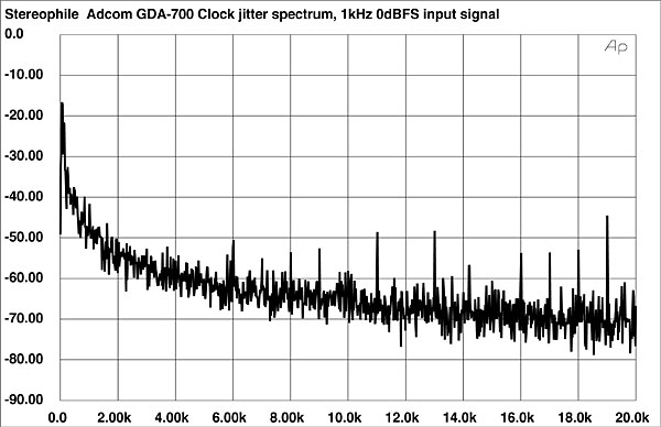
Looking next at the GDA-700's jitter performance, fig.10 shows the jitter spectrum with a 1kHz full-scale sinewave input. The plot shows some periodic jitter components spaced 1kHz apart in the upper part of the band. The RMS jitter level, measured over a 400Hz–20kHz bandwidth, was a low 45 picoseconds.
Fig.10 Adcom GDA-700, word-clock jitter spectrum, DC–20kHz, when processing 1kHz sinewave at 0dBFS; PS Audio Lambda transport (linear frequency scale, 10dB/vertical div., 0dB=1ns).
Fig.11 Adcom GDA-700, word-clock jitter spectrum, DC–20kHz, when processing digital silence; PS Audio Lambda transport (linear frequency scale, 10dB/vertical div., 0dB=1ns).
Fig.12 Adcom GDA-700, word-clock jitter spectrum, DC–20kHz, when processing 1kHz sinewave at –90dBFS; PS Audio Lambda transport (linear frequency scale, 10dB/vertical div., 0dB=1ns).
Footnote 1: Although the AC power-line frequency from a wall outlet is 60Hz, we most often see power-supply noise at 120Hz. The power supply's job is to convert the 60Hz Alternating Current (AC) from the wall outlet into Direct Current (DC) that supplies the component's circuits. Converting AC to DC is called "rectification." An arrangement of diodes called a "full-wave bridge rectifier" essentially inverts one phase of the AC line, the result being 120 pulses per second of the same polarity. Leakage of the rectified 120Hz noise into the analog signal path pollutes the audio signal in some audio components.—Robert Harley


