
Sidebar 3: Measurements
I performed a complete set of measurements on the T+A elektroakustik A 3100 HV Reference with my Prism Sound dScope III audio analyzer and my PicoScope 4824A USB oscilloscope. I took the thermal measurements with a Flir One thermal imager in peak-detect mode.
The T+A A 3100 HV Reference is in effect four user-selectable amplifiers in one. In High Power mode it operates as a classic class-AB design with a normal class-A bias current for that mode. In High Current mode the voltage rails are reduced and the bias current greatly increased, so the class-A region extends to a much higher power. The amplifier also offers stereo and parallel-mono operation; in parallel mono the output power remains voltage-limited, but the damping factor and the peak output current both double. Given this flexibility, I measured the amplifier first in High Power stereo mode, then in High Power mono and High Current stereo modes.
I preconditioned the amplifier in High Power mode by running it at one-eighth the specified power into 8 ohms for 30 minutes. At the end of that time, the temperature of the top plate was 101°F (38°C) and that of the heatsinks 118°F (48°C).
I then ran the amplifier for a further 30 minutes at one-third power into 8 ohms to examine the thermal margin of the output stage. About 18 minutes into that test, the front panel indicated that the output stage had become too hot; in this condition the harmonic distortion at lower powers also rose temporarily. At the end of the 30 minutes the top-panel temperature had risen to a still-reasonable 108°F (42°C), and the heatsinks were hot but still safe to touch casually, at 134°F (57°C). The T+A A 3100 HV Reference has good thermal margin and properly implemented thermal-protection circuitry.
The T+A A 3100 HV Reference preserved absolute polarity, ie, was noninverting, from both its balanced and unbalanced inputs in stereo mode and from the balanced input in parallel-mono mode. The voltage gain at 1kHz into 8 ohms was 26.5dB from the balanced input and 32.4dB from the unbalanced input in stereo mode; the gain was identical in parallel-mono mode. T+A specifies the input impedance as 50k ohms balanced and 25k ohms unbalanced. I measured 23.1k ohms at 20Hz and 1kHz for the unbalanced input, dropping to 19.9k ohms at 20kHz, and 35k ohms at 20Hz and 100Hz for the balanced input, dropping to 32k ohms at 1kHz and 24k ohms at 20kHz.
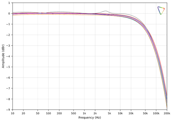
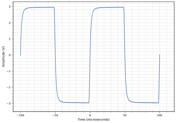
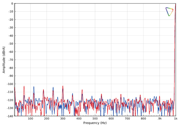
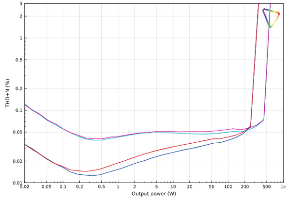
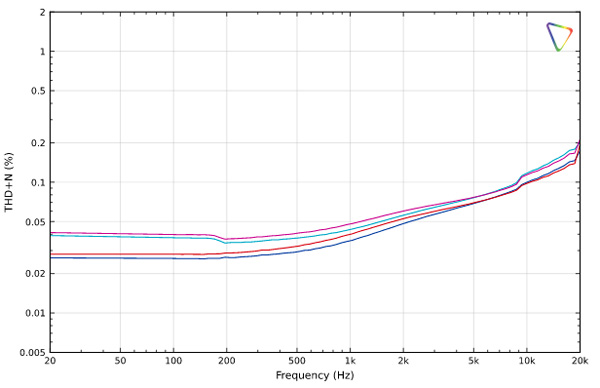
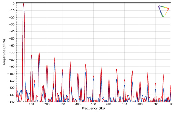
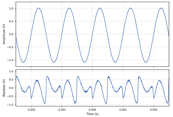
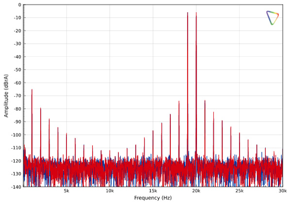
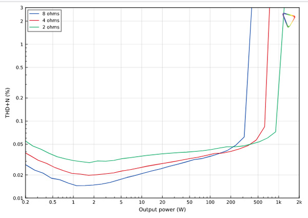
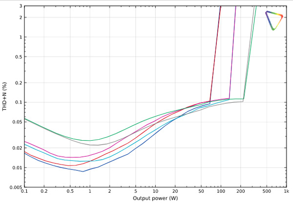
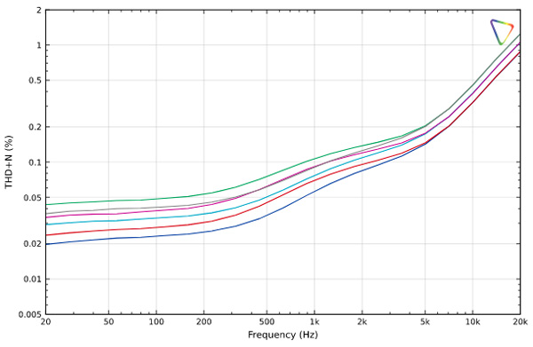
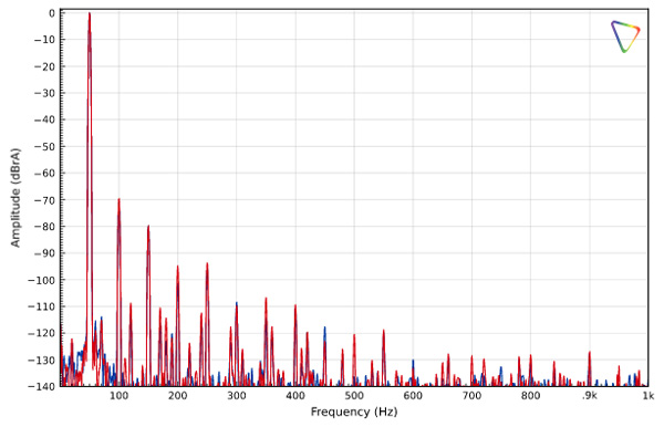
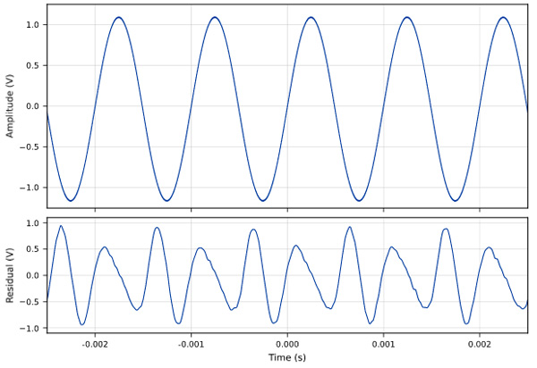
Fig.1 T+A A 3100 HV Reference: Frequency response at 2.83V into: simulated loudspeaker load (gray), 8 ohms (left channel blue, right red), 4 ohms (left cyan, right magenta), and 2 ohms (green) (0.5dB/vertical div.).
Fig.2 T+A A 3100 HV Reference: Small-signal 10kHz squarewave into 8 ohms.
The output impedance in High Power stereo mode was a low 0.04 ohms at low and middle frequencies, rising to 0.125 ohms at the top of the audioband; in High Current mode it dropped to 0.073 ohms at 20kHz. In short, the output impedance of this amplifier is below the resolution of my test fixture. The variation in the amplifier's small-signal frequency response with our standard simulated loudspeaker (fig.1, gray trace) was ±0.3dB. Into 8 ohms (fig.1, blue and red traces), the response was flat throughout the audioband, not reaching –3dB until approximately 150kHz. The T+A A 3100 HV Reference reproduced a 10kHz squarewave (fig.2) without a hint of overshoot or ringing.
Fig.3 T+A A 3100 HV Reference: Low frequency residual spectrum of 1kHz sinewave, DC–1kHz, at 1Wpc into 8 ohms (left channel blue, right red; linear frequency scale).
The T+A A 3100 HV Reference's channel separation (not shown) was 89dB from 20Hz to 5kHz and still 86dB at the top of the audioband. The unweighted, wideband signal/noise ratio in stereo mode (ref. 1W into 8 ohms, taken with the unbalanced inputs shorted to ground) was a decent 79.7dB, averaged across the two channels. Restricting the measurement bandwidth to 22Hz–22kHz improved the ratio to approximately 85dB, and A-weighting improved it further, to 87.5dB in the left channel and 87.3dB in the right. Spectral analysis of the low-frequency noisefloor while the amplifier drove a 1kHz tone at 1Wpc into 8 ohms (fig.3, blue and red traces) revealed a low level of random noise; AC-related spuriae at 60Hz and its odd- and even-order harmonics all lay below –100dB.
Fig.4 T+A A 3100 HV Reference: THD+N versus output power at 1kHz in HPM stereo mode, both channels driven, into: 8 ohms (left channel blue, right red) and 4 ohms (left cyan, right magenta).
T+A specifies the T+A A 3100 HV Reference's maximum power in High Power stereo mode as 300Wpc into 8 ohms and 500Wpc into 4 ohms. With our usual definition of clipping—when the THD+N reaches 1%—the amplifier exceeded its specified power rating. With both channels driven, it clipped at 324Wpc into 8 ohms (fig.4, blue and red traces) and 536Wpc into 4 ohms (fig.4, cyan and magenta traces). I did not test clipping into 2 ohms in stereo mode, but on the basis of the parallel-mono performance into 2 ohms I would expect around 600W, thermally sustainable for music peaks but not for continuous duty.
Fig.5 T+A A 3100 HV Reference: THD+N versus frequency in HPM stereo mode at 20V, equivalent to 50W into 8 ohms (left channel blue, right red) and 100W into 4 ohms (left cyan, right magenta).
Fig.5 shows how the percentage of THD+N varied with frequency in stereo mode at 20V, which is equivalent to 50W into 8 ohms (blue and red traces) and 100W into 4 ohms (cyan and magenta traces). The THD+N was acceptably low throughout the audioband, essentially flat to 1kHz and rising above that frequency, consistent with the reduction in feedback at high frequencies and the phase shift of the feedback.
Fig.6 T+A A 3100 HV Reference: Spectrum of 50Hz sinewave, DC–1kHz, at 50W into 8 ohms, HPM stereo (left channel blue, right red; linear frequency scale).
Fig.7 T+A A 3100 HV Reference: Residual of sinewave 1kHz 50W into 8 ohms, HPM stereo mode; not to scale.
The distortion spectrum of a 50Hz sinewave at 50W into 8 ohms (fig.6) is consistent with a class-AB amplifier using a moderate amount of feedback. The second harmonic is the highest in level, but odd-order harmonics dominate the rest of the spectrum, dropping monotonically as the applied feedback would predict. Note that one channel had elevated odd-order distortion compared with the other, a difference of about 8dB from the seventh harmonic upward. The distortion residual waveform for a 1kHz sinewave at 50W into 8 ohms (fig.7) shows that the second and third harmonics dominate, though some crossover distortion is present at a low level.
Fig.8 T+A A 3100 HV Reference: HF intermodulation spectrum, DC–30kHz, 19+20kHz at 100W peak into 8 ohms, HPM stereo (left channel blue, right red).
Intermodulation distortion was reasonably low in level. With the amplifier driving an equal mix of 19 and 20kHz tones at 100Wpc peak into 8 ohms in stereo mode (fig.8), the 1kHz difference tone lay at –65dB, and the higher-order difference tones dropped with frequency as expected.
Fig.9 T+A A 3100 HV Reference: THD+N versus output power at 1kHz in HPM parallel-mono mode into 8 ohms (blue), 4 ohms (red), and 2 ohms (green).
Reconfiguring the amplifier in High Power mono mode, with the left and right channels paralleled, I retested THD+N against level (fig.9). The 1% clipping points in this configuration were 376W into 8 ohms, 701W into 4 ohms, and a fairly staggering 1107W into 2 ohms.
Fig.10 T+A A 3100 HV Reference: THD+N versus output power at 1kHz in HCM stereo mode, both channels driven, into: 8 ohms (left channel blue, right red), 4 ohms (left cyan, right magenta), and 2 ohms (left green, right gray).
Fig.11 T+A A 3100 HV Reference: THD+N versus frequency in HCM stereo mode at 12.7V, equivalent to 20W into 8 ohms (left channel blue, right red), 40W into 4 ohms (left cyan, right magenta), and 80W into 2 ohms (left green, right gray).
Fig.12 T+A A 3100 HV Reference: Spectrum of 50Hz sinewave, DC–1kHz, at 50W into 8 ohms, HCM stereo (left channel blue, right red).
Fig.13 T+A A 3100 HV Reference: residual of sinewave 1kHz 20W into 8 ohm sinewave, HCM stereo; not to scale.
Switched to High Current mode, the amplifier presented a completely different personality. The distortion at low output powers (fig.10) was lower and did not change significantly with load impedance. The 1% clipping points were 87W into 8 ohms, 156W into 4 ohms, and 283W into 2 ohms. THD+N against frequency at 12.7V RMS into 8, 4, and 2 ohms (fig.11) was very low through 500Hz, rising gently to 5kHz and then more steeply, to approximately 1% at 20kHz. High Current mode may apply less loop feedback than High Power mode. The spectrum of a 50Hz sinewave at 50W into 8 ohms (fig.12) shows the effect of High Current mode as well: the second and third harmonics dominate the distortion spectrum, the fourth and fifth are barely present, at approximately –95dBc, and all other harmonics lie well below –100dBc. The 1kHz distortion residual (fig.13) illustrates the benefit of a high-bias class-A region: the crossover distortion has been completely eliminated, leaving mostly a mix of second- and third-harmonic distortion.
In stereo High Power mode the T+A A 3100 HV Reference performs much as the PA 3100 HV does, but the addition of parallel-mono and High Current modes makes it an attractive amplifier to use either as monoblocks with difficult-to-drive loudspeakers or with lower-impedance or higher-efficiency designs.—Dylan Wahl