Sideabr 2: Measurements
The Vanguard's maximum output level when decoding a full-scale, 1kHz sinewave was 2.25V from the fixed-level outputs and 4.31V from the variable outputs at the highest volume-control setting. These values are 1dB and 6.7dB higher than the standard 2V output, respectively.
Output impedance was a low 50 ohms at any audio frequency from the fixed-level outputs. The variable outputs were similarly low, measuring 65 ohms at 20Hz and 55 ohms through the rest of the band. The combination of low output impedance and high output level suggests that the Vanguard will have no problem driving a power amplifier directly from the variable outputs. However, I measured a rather high 180mV of DC from the left-channel variable output, and a more moderate 17mV from the right. (DC levels from the fixed outputs were below the 100;uV resolution of my voltmeter.) Playing a test CD track of a positive-going impulse produced a negative-going impulse at the outputs, meaning the Vanguard is polarity-inverting. Note that no polarity-inversion switch is provided.
Fig.1 shows the Vanguard's frequency-response (top pair of traces) and de-emphasis error (bottom pair). The Philips digital filter has a significant amount of passband ripple, seen as the waves in the trace as the signal approaches the stopband. There's also a slightly rising response in the top octave. The Vanguard had a slight positive de-emphasis error in the left channel (solid trace), and a minor negative error in the right (dotted trace). If this de-emphasis–error trace looks a little different from the usual traces in my digital processor reviews, it's because CD-player testing requires use of the discrete de-emphasis test signals on a test CD (125Hz, 1kHz, 4kHz, 16kHz). Digital processors are driven by a swept sinewave from Audio Precision's DSP signal generator.
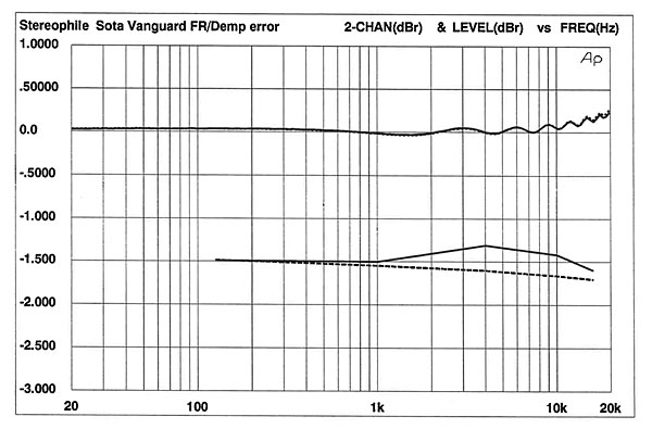
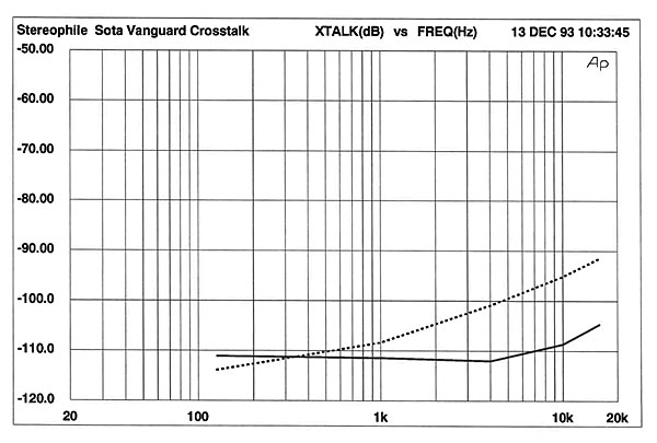
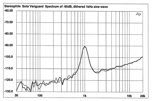
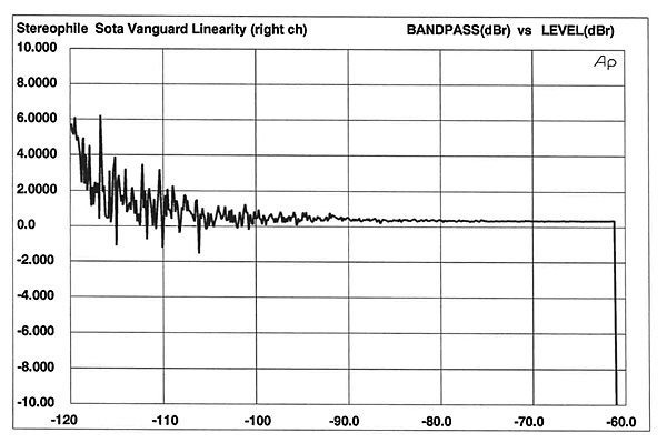
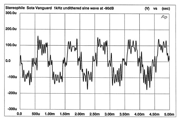
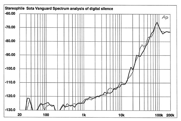 Fig.5 confirms the Vanguard's excellent low-level linearity. The unit is virtually perfect to –105dB, where noise begins to dominate the measurement. The right channel is shown; the left was identical. This excellent low-level linearity is characteristic of the Philips TDA1547 DAC used in the Vanguard. Another indicator of low-level performance is provided by fig.6, the Vanguard's reproduction of an undithered, 1kHz sinewave. The waveform has excellent shape and symmetry.
 Finally, I measured the Vanguard's tracking ability by playing the series of tracks on the Pierre Verany Test CD that has increasingly long data dropouts in the spiral track. The higher the track number the player will play without skipping, the better its tracking ability. The Vanguard played through track 33, but fell apart at track 34. This is average performance.
Overall, the Vanguard performed well on the bench. The good linearity, absence of power-supply noise, and low level of intermodulation products indicated good engineering.—Robert Harley
Finally, I measured the Vanguard's tracking ability by playing the series of tracks on the Pierre Verany Test CD that has increasingly long data dropouts in the spiral track. The higher the track number the player will play without skipping, the better its tracking ability. The Vanguard played through track 33, but fell apart at track 34. This is average performance.
Overall, the Vanguard performed well on the bench. The good linearity, absence of power-supply noise, and low level of intermodulation products indicated good engineering.—Robert Harley
Fig.1 SOTA Vanguard II, frequency response (top) and de-emphasis error (bottom) (right channel dashed, 0.5dB/vertical div.).
Channel separation (fig.2) was excellent, measuring roughly 110dB at 1kHz, decreasing to 105dB (left channel) and 92dB (right) at 16kHz. The right-left channel crosstalk (dotted trace) increases with frequency more than the left-right channel.
Fig.2 SOTA Vanguard II, crosstalk (right–left dashed, 10dB/vertical div.).
A spectral analysis of the Vanguard's output when playing a –90dB, dithered 1kHz sinewave is shown in fig.3. The overall noise level is low, with a slightly rising response above 10kHz, the result of the DAC's noise shaping. The DAC appears very linear—the peaks just reach the –90dB horizontal division. In addition, the traces overlap, indicating that the left- and right-channel DACs are performing nearly identically. The low-frequency range is almost free from power-supply–related noise. There's just a hint of 60Hz hum in both channels, and a trace of 120Hz noise in the right channel. This is, however, excellent immunity from power-supply noise, particularly since the large transformer is in the same chassis as the audio circuits.
Fig.3 SOTA Vanguard II, spectrum of dithered 1kHz tone at –90.31dBFS, with noise and spuriae (1/3-octave analysis, right channel dashed).
A wider-bandwidth spectral analysis (fig.4), made when the Vanguard was playing a track of all zeros, more clearly shows the effects of noise-shaping. The noise rises rapidly in the top octave all the way to the peak at 90kHz. Note the small peaks at 18kHz and 36kHz in the left channel.
Fig.4 SOTA Vanguard II, spectrum of silent track, 20Hz–200kHz, with noise and spuriae (1/3-octave analysis, right channel dashed).
Fig.5 SOTA Vanguard II, right channel, departure from linearity (left channel identical, 2dB/vertical div.).
Fig.6 SOTA Vanguard II, waveform of undithered 1kHz sinewave at –90.31dBFS.
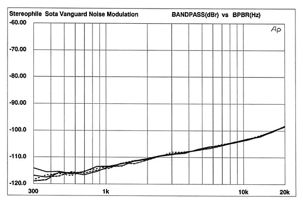
The Vanguard's noise-modulation performance (fig.7) was similarly impressive. The traces nearly perfectly overlap above 1kHz, indicating that the Vanguard's noise floor doesn't shift in level or change spectrally as a function of input level. This isn't surprising, since performance on this test is related to low-level linearity, which, as we have already seen, was excellent.
Fig.7 SOTA Vanguard II, noise modulation, –60 to –100dBFS (10dB/vertical div.).
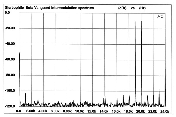
Fig.8 is an FFT of the Vanguard's output when decoding a full-scale mix of 19kHz and 20kHz. The 1kHz intermodulation product (20kHz minus 19kHz) is well down in level (–112dB), and the spurious components on either side of the test-signal frequencies are also extremely low. This is exemplary performance.
Fig.8 SOTA Vanguard II, HF intermodulation spectrum, DC–22kHz, 19+20kHz at 0dBFS (linear frequency scale, 20dB/vertical div.).
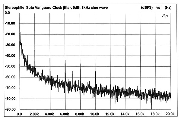
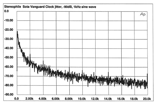
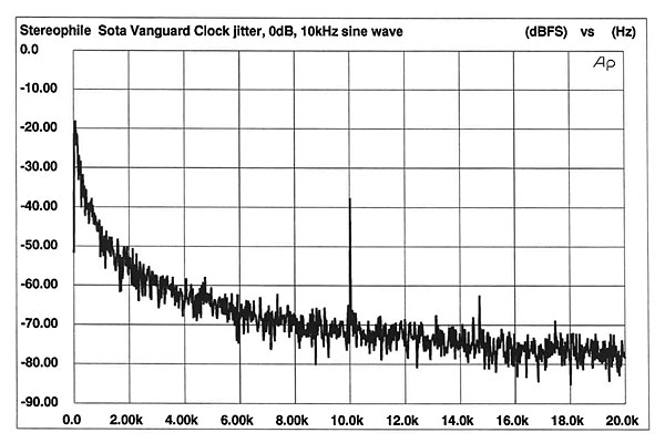
The Vanguard's jitter performance was also good. I measured between 29 and 31 picoseconds (RMS, 400Hz–22kHz bandwidth) of clock jitter with any test signal. The RMS levels remained virtually unchanged, regardless of the input signal. These RMS values were measured on the 128fs clock signal (5.6448MHz). If we relate 30ps of clock jitter to the clock period, this is equivalent to 490ps of clock jitter on an 8x-oversampling clock. Note, however, that 1-bit DACs such as the TDA1547 used in the Vanguard react very differently to clock jitter than do multi-bit DACs. Moreover, 1-bit DACs are influenced by jitter well above 40kHz, the highest jitter frequency that can affect multi-bit DACs. (This issue is discussed in depth in Rémy Fourré's article on jitter in the October 1993 Stereophile.)
An FFT of the jitter spectrum when the Vanguard was decoding a full-scale, 1kHz sinewave is shown in fig.9. Notice the signal-related spikes at 1kHz and its multiples. Apart from a few signal-related periodic jitter components, the spectrum is fairly clean. Fig.10 is the jitter spectrum with a –90dB, 1kHz sinewave input. We can still see some signal-correlated jitter at multiples of the test signal, but they're lower in level. The fewer signal-correlated jitter components at a low signal level is the opposite of what happens to a digital processor's jitter. The S/PDIF interface between a transport and processor introduces higher jitter at lower signal levels because low-level signals create more bit transitions, which in turn create interface jitter that winds up at the DAC's word clock. A CD player, with no need for the S/PDIF interface, has an inherent advantage in jitter performance over a separate CD transport and digital processor connected by the S/PDIF interface. The Vanguard isn't completely immune to signal-correlated jitter, however, as shown by the spike at 10kHz in fig.11. This is the Vanguard's jitter spectrum when playing a full-scale, 10kHz sinewave. Note, however, the relative absence of spikes in the spectrum.
Fig.9 SOTA Vanguard II, word-clock jitter spectrum, DC–20kHz, when processing 1kHz sinewave at 0dBFS (linear frequency scale, 10dB/vertical div., 0dB = 1ns).
Fig.10 SOTA Vanguard II, word-clock jitter spectrum, DC–20kHz, when processing 1kHz sinewave at –90dBFS (linear frequency scale, 10dB/vertical div., 0dB = 1ns).
Fig.11 SOTA Vanguard II, word-clock jitter spectrum, DC–20kHz, when processing 10kHz sinewave at 0dBFS (linear frequency scale, 10dB/vertical div., 0dB = 1ns).


