Sidebar 3: Measurements
I performed a full set of measurements on the Linear Tube Audio microZOTL2.0 using my Audio Precision SYS2722 system (see the January 2008 "As We See It"). The three sets of outputs—headphone, RCA jacks, speaker terminals—are connected in parallel, with a shunt 470k ohm resistor connecting the hot connection to ground. I therefore took most of the measurements from the RCA jacks. Because the amplifier's unique output stage uses an RF oscillator modulated with the audio signal, there was around 7mV of RF noise present on its output, so I experimented with using the Audio Precision passive low-pass filter to eliminate the effect of this noise, as well as a brickwall filter at 20kHz for the distortion measurements.
The maximum voltage gain was a low 12.9dB, and the microZOTL2.0 preserved absolute polarity. The input impedance was relatively high, ranging from 46k ohms at low and middle frequencies to 36.5k ohms at the top of the audioband. The output impedance was 2 ohms across most of the audioband, as specified, increasing slightly to 2.35 ohms at 20kHz.
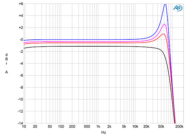
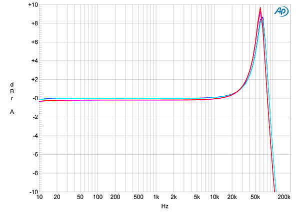
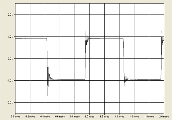
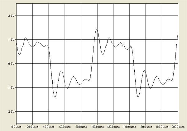
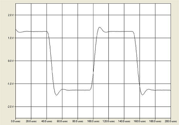
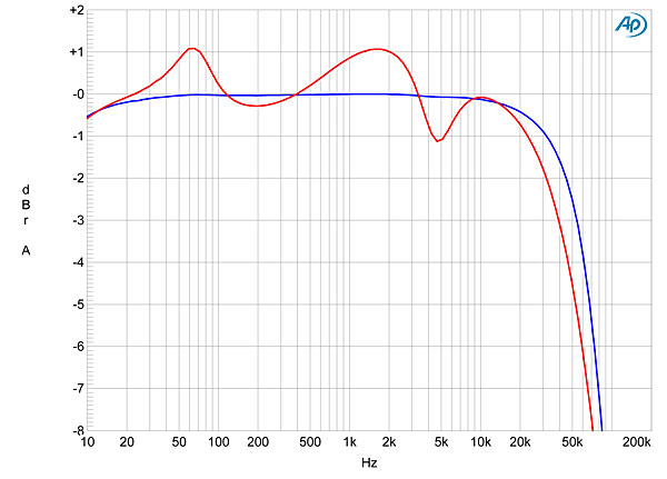
In terms of frequency response, the two channels matched very closely and, commendably, the response was not affected by the volume-control setting. However, an ultrasonic peak between 60 and 70kHz became more accentuated the higher the load impedance (fig.1), which, in the extreme case—into the analyzer's 100k ohms impedance (fig.2)—resulted in overshoot and ringing with both 1kHz (fig.3) and 10kHz (fig.4) squarewaves. At the other extreme, with a 10 ohm load, the gray trace in fig.1 indicates that the peak has been suppressed, and the 10kHz squarewave has a single damped cycle of ringing (fig.5). David Berning's ZOTL patent claims load-tolerant behavior for the design, but with its 2 ohm output impedance, the response varied by ±1.1dB with our standard simulated loudspeaker (fig.6, red trace).
 David Berning's TF-10 preamplifier was the late J. Gordon Holt's reference for many years at the end of the 1970s, so I was not surprised to find that this unusual design measured well in some respects, particularly in how its linearity was not affected by the load impedance. And where the microZOTL2.0 didn't measure so well, the shortfall seemed to have been carefully managed to have a minimal effect on music at typical headphone-playback levels.—John Atkinson
Footnote 1: Subsequent to this review, Linear Tube Audio suggested that these spuriae stem from the wall-wart supply that they buy-in from a third-party supplier. They are introducing a dedicated supply for the MicroZOTL2.0 that won't have this problem.
Fig.1 Linear Tube Audio microZOTL2.0, frequency response at 1V into: 100 ohms (blue), 30 ohms (magenta), 20 ohms (red), 10 ohms (gray) (2dB/vertical div.).
Fig.2 Linear Tube Audio microZOTL2.0, frequency response at 1V into 100k ohms (2dB/vertical div.).
Fig.3 Linear Tube Audio microZOTL2.0, small-signal, 1kHz squarewave into 100k ohms.
Fig.4 Linear Tube Audio microZOTL2.0, small-signal, 10kHz squarewave into 100k ohms.
Fig.5 Linear Tube Audio microZOTL2.0, small-signal, 10kHz squarewave into 10 ohms.
Fig.6 Linear Tube Audio microZOTL2.0, frequency response at 1V into 8 ohms (blue), simulated loudspeaker load (red) (1dB/vertical div.).
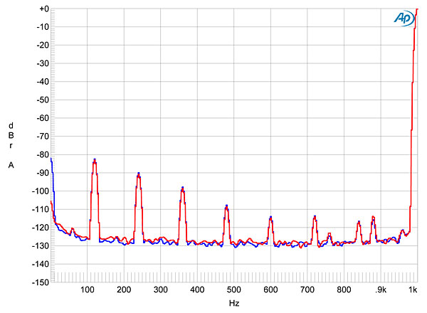
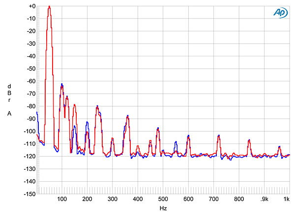
Channel separation was good, at >80dB below 10kHz, but the unweighted, wideband signal/noise ratio, measured with the inputs shorted to ground but the volume control set to its maximum, was disappointing, at 42.9dB left and 44.1dB right, both figures ref. 1V into 100k ohms. These ratios are dominated by the RF leakage, of course, and restricting the measurement bandwidth to the audioband respectively increased them to 81.5 and 82.1dB. A-weighting the measurement gave further improvement, to 94.1 and 94.6dB. To my surprise, given that the microZOTL2.0 is powered by a 12V DC switching supply, the spectrum of the low-frequency noise floor revealed spuriae at the full-wave–rectified frequency of 120Hz and its multiples (fig.7). Usually, this suggests that I have inadvertently introduced a ground loop in the test setup, and it is fair to note that these spuriae are still at a low level: –83dB and lower. However, nothing I could do in varying the ground connections between the amplifier and the test system eliminated the 120Hz-related spuriae (footnote 1).
Fig.7 Linear Tube Audio microZOTL2.0, spectrum of 1kHz sinewave, DC–1kHz, at 1V into 100k ohms (linear frequency scale).
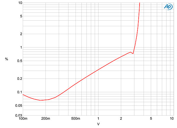
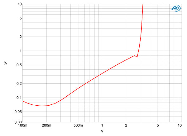
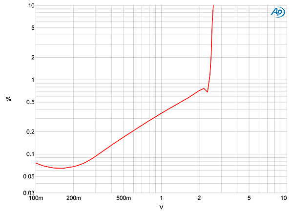
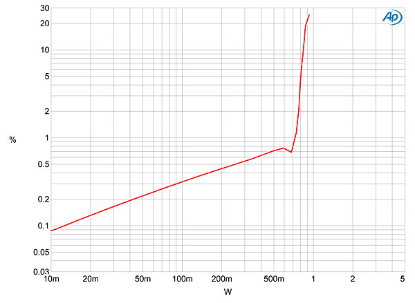
Where the microZOTL2.0 did prove tolerant of the load impedance was in its linearity. Figs. 8, 9, 10, and 11 plot the percentage of THD+noise against output voltage into 300, 30, 8, and 4 ohms, respectively. You can see that, other than the slight reduction in maximum output voltage, due to the interaction between the microZOTL2.0's 2 ohm output impedance and the load impedance, the shape of the traces in these three graphs is identical. The THD+N percentage is dominated by noise below 200mV or so, and once the distortion starts to rise above the noise, it remains below 0.1% below 350mV before gradually rising with increasing voltage. The output stage clips (defined as 1% THD+N) at 2.9V into 30 ohms, an impedance that is typical of low-impedance headphones, but the clipping voltage into 8 ohms drops to 2.6V, which is equivalent to 0.85W. So while Herb Reichert found he could get acceptably loud levels in his fairly small room using the microZOTL2.0 to drive high-sensitivity, high-impedance speakers, I wouldn't recommend this amplifier for driving more typical speakers in large spaces.
Fig.8 Linear Tube Audio microZOTL2.0, THD+N (%) vs 1kHz continuous output voltage into 300 ohms.
Fig.9 Linear Tube Audio microZOTL2.0, THD+N (%) vs 1kHz continuous output voltage into 30 ohms.
Fig.10 Linear Tube Audio microZOTL2.0, THD+N (%) vs 1kHz continuous output voltage into 8 ohms.
Fig.11 Linear Tube Audio microZOTL2.0, THD+N (%)vs 1kHz continuous output voltage into 8 ohms.
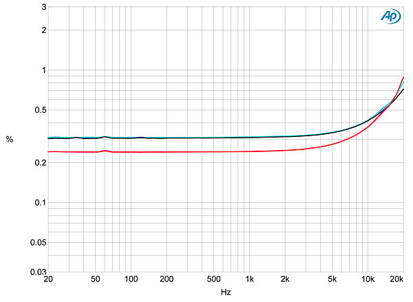
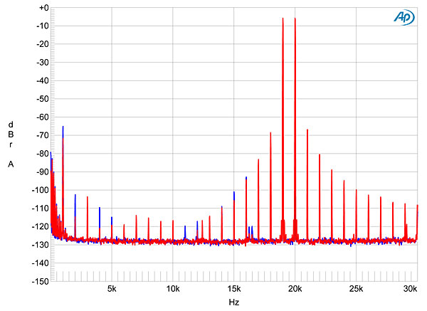
I plotted how the THD+N percentage varied with frequency at a level, 1V, that would be around the highest a user would encounter while using the microZOTL2.0 as a preamplifier or headphone amplifier. The right channel (fig.12, red, magenta, gray traces) was slightly more linear than the left (blue, cyan, green); but, as suggested by figs.8–11, though the actual THD+N was relatively high at this output level, it didn't change with the load impedance. The amplifier's distortion signature was dominated by the subjectively benign second harmonic (fig.13), and despite the decreasing linearity at the top of the audioband seen in fig.10, an equal mix of 19 and 20kHz tones produced relatively low levels of intermodulation products (fig.14).
Fig.12 Linear Tube Audio microZOTL2.0, THD+N (%) vs frequency at 1V into: 100k ohms (left channel blue, right red), 600 ohms (left cyan, right magenta), 30 ohms (left green, right gray).
Fig.13 Linear Tube Audio microZOTL2.0, spectrum of 50Hz sinewave, DC–1kHz, at 300mV into 100k ohms (linear frequency scale).
Fig.14 Linear Tube Audio microZOTL2.0, HF intermodulation spectrum, DC–30kHz, 19+20kHz at 1V peak into 100k ohms (linear frequency scale).
Footnote 1: Subsequent to this review, Linear Tube Audio suggested that these spuriae stem from the wall-wart supply that they buy-in from a third-party supplier. They are introducing a dedicated supply for the MicroZOTL2.0 that won't have this problem.


