Sidebar 2: Measurements
The DSP-1000's maximum output level when decoding a full-scale, 1kHz sinewave was a low 0.93V, more than 6dB below the standard output level of 2V. Because the DSP-1000 had been retrofitted with the PMD100 digital filter/HDCD decoder chip, I suspect that EAD left the analog stage gain alone and attenuated the signal 6dB in the digital domain with the PMD100 and accepted the low output level. This won't be a problem with most preamps, since 1V is still plenty of signal to drive a preamplifier. When comparing the DSP-1000 to other processors, however, be sure to match levels or the DSP-1000 will be at a disadvantage.
Output impedance measured a low 50 ohms across the band, and DC levels were negligible. The unit doesn't invert absolute polarity, and locked to 32kHz and 48kHz sampling frequencies.
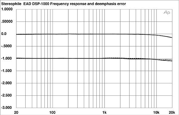
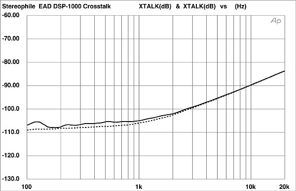
Fig.1 shows the DSP-1000's frequency response and de-emphasis error. The response is flat, and the unit has no de-emphasis mistracking. Channel separation (fig.2) was excellent, measuring 105dB at 1kHz, but decreasing to a still good 84dB at 20kHz.
 This is of little consequence to most users. Unless you have professional source components with 20-bit output, or Audio Alchemy's DTI Pro or DTIPro 32 (which provide up to 20-bit output from 16-bit sources), it won't matter that the DSP-1000 won't pass 20-bit data. You should be aware of this condition, however, and not assume that any processor with the PMD100 and 20-bit DACs will always pass 20-bit data.
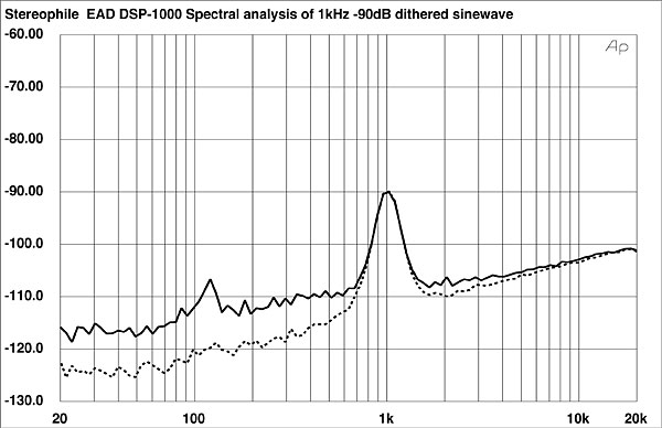
With that caveat, the spectral analysis of the DSP-1000's output when decoding a 1kHz, –90dB sinewave with 16-bit resolution is shown in fig.3. The right channel's noise floor (dotted trace) is about 8dB lower in level than the left channel's. We can also see a trace of second-harmonic distortion in the left channel, along with what is probably power-supply noise at 120Hz. Although the two DACs appear to be performing identically (the traces overlap at the test-signal frequency), the unit's analog noise floor is different in the two channels.
This is of little consequence to most users. Unless you have professional source components with 20-bit output, or Audio Alchemy's DTI Pro or DTIPro 32 (which provide up to 20-bit output from 16-bit sources), it won't matter that the DSP-1000 won't pass 20-bit data. You should be aware of this condition, however, and not assume that any processor with the PMD100 and 20-bit DACs will always pass 20-bit data.
With that caveat, the spectral analysis of the DSP-1000's output when decoding a 1kHz, –90dB sinewave with 16-bit resolution is shown in fig.3. The right channel's noise floor (dotted trace) is about 8dB lower in level than the left channel's. We can also see a trace of second-harmonic distortion in the left channel, along with what is probably power-supply noise at 120Hz. Although the two DACs appear to be performing identically (the traces overlap at the test-signal frequency), the unit's analog noise floor is different in the two channels.
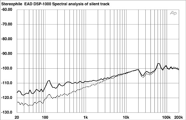
 We can see this situation again in fig.4, a wideband spectral analysis of the DSP-1000's output when decoding an input signal of all zeros. The 120Hz power-supply noise is confirmed, as is the disparity in noise floor between channels. Above 20kHz, you can also see what almost looks like filter ripple, with peaks apparent at 32kHz, 64kHz, and 96kHz.
 Overall, the DSP-1000's mostly excellent technical performance was marred by its less-good reproduction of low-level waveforms.—Robert Harley
Fig.1 EAD DSP-1000 III, frequency response (top) and de-emphasis error (bottom) (right channel dashed, 0.5dB/vertical div.).
Fig.2 EAD DSP-1000 III, crosstalk (R–L channel dashed, 10dB/vertical div.).
The measurements were proceeding when I got a strange result from the spectral analysis of a 1kHz, –90dB dithered sinewave; the DSP-1000 had poor linearity and lots of harmonic distortion. Switching the input word length from 20-bit to 16-bit revealed the cause of the unusual measurement result: the DSP-1000 will pass 16-bit data, but not 20-bit. Consequently, the dither at the LSB of the 20-bit word was truncated along with the four LSBs, meaning the DSP-1000 was decoding an undithered 16-bit sinewave.
When the DSP-1000 was retrofitted with a daughterboard to replace the 16-bit NPC filter with the 20-bit PMD100, the motherboard apparently wasn't changed. So although the PMD100 filter will pass up to 24-bit data, and the DACs are 20-bit, the DSP-1000 will truncate longer input word lengths down to 16-bits. The rest of the measurements are therefore made with 16-bit input signals.
Fig.3 EAD DSP-1000 III, spectrum of dithered 1kHz tone at –90.31dBFS, with noise and spuriae (16-bit data, 1/3-octave analysis, right channel dashed).
Fig.4 EAD DSP-1000 III, spectrum of digital silence (16-bit data, 1/3-octave analysis, right channel dashed).
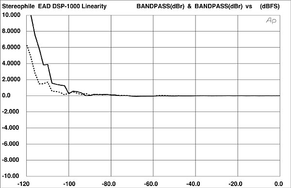
The DSP-1000's linearity (fig.5) was good, but not exceptional. Again, we see the left channel's higher noise, which intrudes on the linearity measurement (the solid left-channel trace rises more quickly than does the dotted right-channel trace).
Fig.5 EAD DSP-1000 III, departure from linearity (right channel dashed, 2dB/vertical div.).
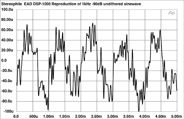
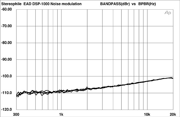
Fig.6 is the DSP-1000's reproduction of a 1kHz, –90dB undithered sinewave. The DACs apparently have some differential non-linearity, seen as the greater amplitude of the –1 step compared to the +1 step. In other words, the negative-going phase of the reproduced sinewave has greater amplitude than the positive-going phase. [This asymmetry is generally associated with the production of even-order harmonic distortion.—Ed.] We can also see a fair amount of noise overlaying the waveform, and the waveshape is not as good as is generally seen with 1995-vintage processors. (For an exemplary waveshape, see the Classé DAC 1's reproduction of this waveform elsewhere in this issue.) The DSP-1000's noise modulation (fig.7) was good, however, with very tight trace groupings above 1kHz and small deviations below that frequency.
Fig.6 EAD DSP-1000 III, waveform of undithered 1kHz sinewave at –90.31dBFS (16-bit data).
Fig.7 EAD DSP-1000 III, noise modulation, –60 to –100dBFS (10dB/vertical div.).
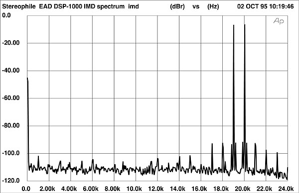
Looking next at the unit's intermodulation spectrum (fig.8), the audioband is clean and free from IMD components. Unusually, however, the test signal frequencies of 19kHz and 20kHz (mixed together at full-scale) have narrowly spaced sidebands around them, a situation I haven't seen before. These intermodulation products however, do lie below –90dB.
Fig.8 EAD DSP-1000 III, HF intermodulation spectrum, DC–24kHz, 19+20kHz at 0dBFS (linear frequency scale, 20dB/vertical div.).
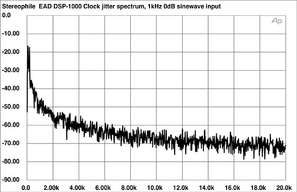
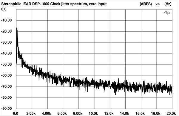
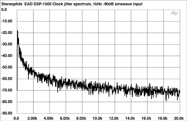
Finally, the DSP-1000 had superb jitter performance. Under all input signal conditions, the spectrum was free from periodic jitter components, and the RMS level was extremely low. Specifically, the DSP-1000's jitter spectrum taken with the unit decoding a 1kHz, full-scale sinewave (fig.9) is perfectly clean. The RMS level was 40ps, an exceptionally low level. With an input signal of all zeros, the RMS jitter level was unchanged, and the spectrum was very slightly cleaner (fig.10). With the more demanding input signal of a 1kHz, –90dB sinewave, the spectrum was again perfectly free from periodic jitter components (fig.11), and the RMS level was again unchanged at 40ps. The DSP-1000's excellent ability to reject jitter in the incoming datastream regardless of input amplitude is exceptional, and indicates that EAD's "Digital Flywheel" jitter-reduction circuit works well.
Fig.9 EAD DSP-1000 III, word-clock jitter spectrum, DC–20kHz, when processing 1kHz sinewave at 0dBFS; PS Audio Lambda transport (linear frequency scale, 10dB/vertical div., 0dB=1ns).
Fig.10 EAD DSP-1000 III, word-clock jitter spectrum, DC–20kHz, when processing digital silence; PS Audio Lambda transport (linear frequency scale, 10dB/vertical div., 0dB=1ns).
Fig.11 EAD DSP-1000 III, word-clock jitter spectrum, DC–20kHz, when processing 1kHz sinewave at –90dBFS; PS Audio Lambda transport (linear frequency scale, 10dB/vertical div., 0dB=1ns).