| Columns Retired Columns & Blogs |
An excellent review. If this model is half as good as the AX-5 Integrated, it is a keeper.
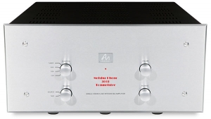
On its face, the Ayre Acoustics EX-8 2.0 Integrated Hub appears identical to the original EX-8 that I reviewed in February 2019. However, changes have been made to better allow the amplifier to drive low impedances (footnote 1). I measured the EX-8 2.0 with my Audio Precision SYS2722 system (see the January 2008 "As We See It") and repeated some of the tests with the magazine's APx500 system. Before performing any testing, I followed the CEA's recommendation of operating the EX-8 2.0 at one-eighth the specified power into 8 ohms for 30 minutes. At the end of that period, its top panel was a little warmer than the EX-8's had been, at 113.1°F (45.1°C), and the bottom panel, which acts as the heatsink for the output devices, was too hot to touch, at 133.6°F (56.4°C). Owners of the EX-8 2.0 need to ensure that the amplifier is well ventilated.
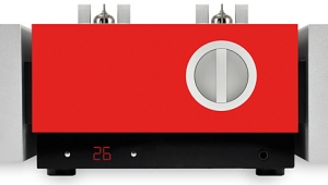
I started the measurements with the line-level analog inputs. With the volume control at its maximum setting, the voltage gain at 1kHz into 8 ohms measured 26dB from the speaker terminals for both balanced and unbalanced inputs. Though this is low for an integrated amplifier, there won't be any issues with regular line-level source components. The maximum gain from the single-ended headphone output was 4.76dB for the balanced input and 4.5dB for the unbalanced input. The maximum gain at the Preamp/Sub outputs was 8.7dB for the balanced input to balanced output, 2.4dB for unbalanced input to unbalanced output. The line inputs preserved absolute polarity (ie, were noninverting) from all outputs. The unbalanced input impedance was 18.6k ohms at low and middle frequencies, dropping very slightly to 16.3k ohms at 20kHz. The balanced input impedance was twice the unbalanced value, as expected. While these impedances are much lower than the specified values of 1M ohm, unbalanced, and 2M ohm, balanced, they are very similar to those of the original EX-8 and high enough not to load down source components.
The single-ended headphone output impedance was an appropriately low 3 ohms at all audio frequencies. The Preamp/Sub output impedance was a still-low 129 ohms, unbalanced, and 258 ohms, balanced. The left channel's output impedance at the speaker terminals (including the series impedance of 6' of spaced-pair loudspeaker cable) was 0.35 ohm from 20Hz to 20kHz. This is slightly lower than that of the original EX-8, but the right channel's output impedance was higher, at 0.525 ohms. The left channel's output impedance resulted in a modulation of the frequency response with our standard simulated loudspeaker of ±0.3dB (fig.1, gray trace). The response was flat to 20kHz into 8 ohms (fig.1, blue and red traces), rolling off above the audioband to reach –3dB above 200kHz. The right channel's level (red and magenta traces) was slightly lower than the left's (blue and cyan traces), presumably due to the higher output impedance. (The channels were more closely matched from the Preamp/Sub and headphone outputs, fig.2.)
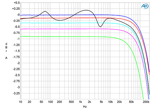
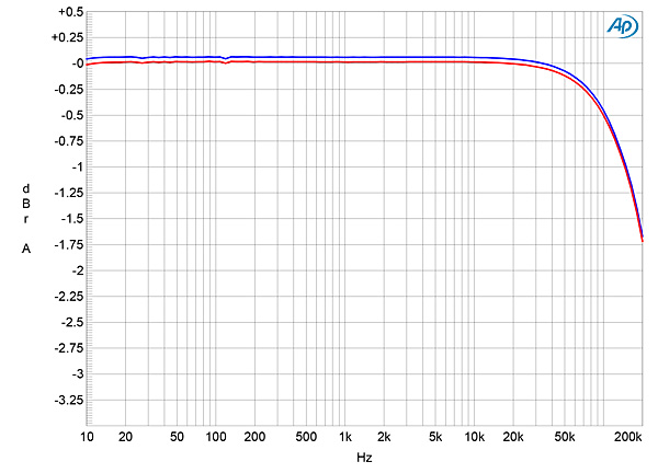
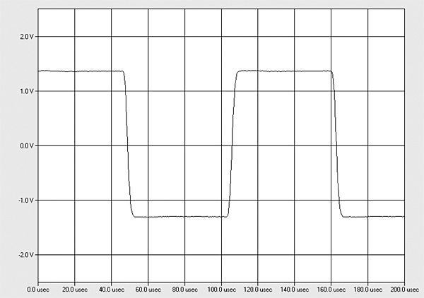
Figs.1 and 2 were taken with the volume control set to its maximum; the response didn't change at lower volume settings. However, an imbalance developed in favor of the right channel at lower settings of the volume control, reaching a maximum difference of 0.9dB at –20dB. (The EX-8's volume control behaved identically, except that the level imbalance at low volume control settings favored the left channel.) The EX-8 2.0's reproduction of a 10kHz squarewave (fig.3) was superbly square, with short risetimes and no overshoot or ringing.
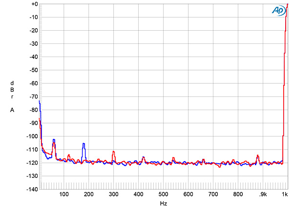
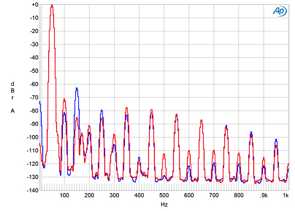
Channel separation was excellent, at >100dB in both directions below 2kHz, decreasing to 80dB at 20kHz, due to capacitive coupling between the channels. With the single-ended analog inputs shorted to ground and the volume control set to its maximum, the wideband, unweighted signal/noise ratio (ref. 2.83V into 8 ohms) measured 75.35dB (average of both channels), which is superb. Restricting the measurement bandwidth to 22kHz increased the ratio to 86.2dB, and an A-weighting filter increased it further, to 88.45dB. As with the EX-8, the levels of residual spuriae at the AC power-line frequency and its harmonics were very low, particularly in the right channel (fig.4, red trace).
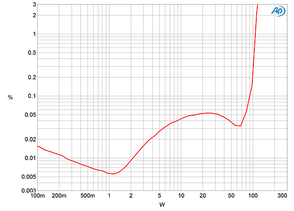
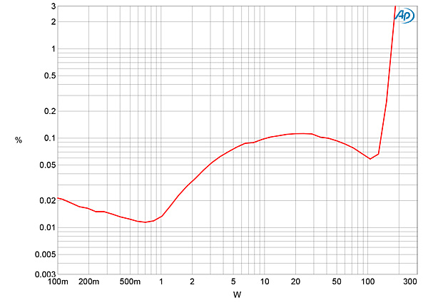
Like its predecessor, the EX-8 2.0 is specified to deliver a maximum continuous output power of 100Wpc into 8 ohms (20dBW). At our usual definition of clipping (ie, when the percentage of THD+noise in the amplifier's output reaches 1%), the Ayre delivered 107Wpc into 8 ohms with continuous drive in both channels (fig.5, 20.3dBW). With both channels driven into 4 ohms, the EX-8 2.0 clipped at the specified 170Wpc (fig.6, 19.3dBW), compared with the EX-8's 125Wpc (18dBW). The distortion was low below 1W into either impedance, but rose at a few tens of watts, then decreased slightly before actual waveform clipping occurred.
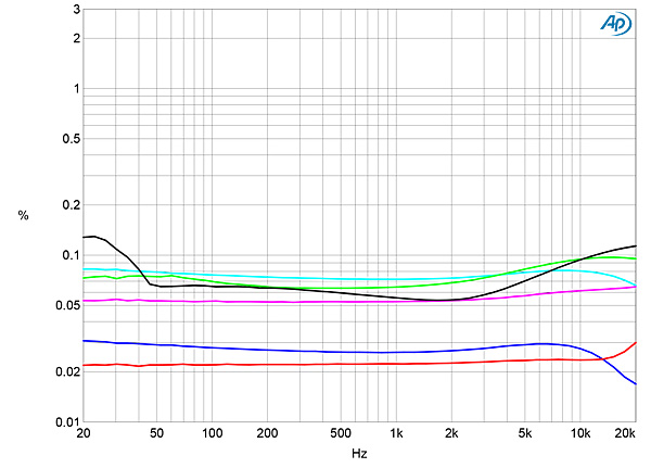
Levels of distortion measured against frequency at 8.95V—equivalent to 10W into 8 ohms, 20W into 4 ohms, and 40W into 2 ohms—were respectably low into the two higher impedances (fig.7, blue, red, cyan, and magenta traces). Notably, the EX-8 2.0 had significantly lower distortion than the EX-8 at this voltage into 2 ohms (green and gray traces). The THD+N percentages into 2 ohms were lower than the left channel's into 4 ohms (cyan trace); this was due to the fact that I could only measure one channel at a time into 2 ohms. With both channels driven at 40W into 2 ohms, the amplifier turned itself off halfway through the measurement because it detected excessive temperature, according to the front-panel display. Putting the Ayre into sleep mode, by pressing the left-hand button on the front panel for more than 3 seconds, then turning it on again brought the amplifier back into operation.
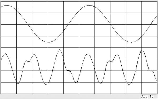
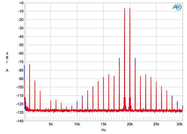
The shape of the left channel's distortion-spuriae waveform indicated that the EX-8 2.0's harmonic distortion was predominantly third harmonic in nature (fig.8). Spectral analysis indicated that the third harmonic was the highest in level in the left channel (fig.9, blue trace), the second the highest in the right channel (red trace), with higher odd-order harmonics present at lower levels in both channels. Second-order intermodulation distortion at moderate power into 8 ohms was very low, the difference product at 1kHz resulting from an equal mix of 19 and 20kHz tones lying at –96dB in the left channel and –86dB in the right (fig.10). Higher-order products were present at higher levels, and the level of the difference product at 1kHz increased to –73dB when I repeated the test at the same power level into 4 ohms (fig.11).

Turning to the digital inputs, the EX-8 2.0's AES/EBU and coaxial and optical S/PDIF inputs locked to datastreams with all sample rates up to 192kHz and preserved absolute polarity. Apple's USB Prober utility identified the EX-8 2.0 as "Ayre USB Interface" from "Ayre Acoustics" with the serial number "Streamlength(tm)." USB Prober confirmed that the EX-8 2.0's USB port operates in the optimal isochronous asynchronous mode. The AudioMIDI utility revealed that the EX-8 2.0's USB port could handle 24-bit integer data at all sample rates up to 384kHz. A 1kHz digital signal at –12dBFS resulted in an output level of 18.46V into 8 ohms from the speaker outputs, 2.46V from the balanced Preamp/Sub outputs, and 1.55V with the volume control at its maximum setting. All of these are approximately 4dB below the clipping voltage from the outputs, which suggests that the digital inputs have about 8dB too much gain. However, a menu item allows the maximum level for the digital inputs to be reduced in 6dB steps. (It had been set to the maximum for KM's auditioning.) I tested the digital inputs from the single-ended headphone output and from the balanced Preamp/Sub output with the level reduced by 8dB with the volume control.
I haven't discussed the EX-8 2.0's performance via its digital inputs, as this was identical to that of the original EX-8, with a short, minimum-phase, slow-rolloff reconstruction filter, between 18 and 19 bits of usable resolution, and a large number of aliasing products visible with high-level, high-frequency tones (footnote 2).
Ayre's EX-8 2.0 Integrated Hub does handle low impedances more gracefully than the EX-8 and delivers its specified power into 4 ohms. Like its predecessor, its measured performance is dominated by the decision not to use loop negative feedback in its design. I was also puzzled by the somewhat different output impedances and distortion signatures of the two channels (footnote 3). I can't help but wonder if this is due to current supply-chain problems, which could make it difficult to obtain optimally matched output devices (footnote 4), as nonoptimal matching would be exacerbated by the absence of overall negative feedback.—John Atkinson
Footnote 2: See my measurements here.
Footnote 3: Following publication of the review, Ayre suspected that a solder joint for one of the output devices in the right channel had failed when the amplifier suffered a shock when it was sent to my place for the measurements. I will report on the measured performance of a second sample in the December 2021 issue.
Footnote 4: This problem was examined in Re-Tales #11 and this YouTube video.
|
|
| ||||||||||

An excellent review. If this model is half as good as the AX-5 Integrated, it is a keeper.
I guess this proves, once again, that all manufacturers send special high performance non-standard products to reviewers for review in front of the world.
(Insert rolling eyes emoji here.)
what this proves,once more,is that inadequate packing equates to manufacturer profit and customer loss.
Umm...
"It appeared that the review sample had suffered some kind of shock in transit from Ken Micallef's place to mine—the top panel was dented—"
That's on the manufacturer? They didn't do the packaging for that part of the journey. You still could be right, but...


| Loudspeakers Amplification Digital Sources | Analog Sources Accessories Featured | Music Columns Retired Columns | Show Reports | Features Latest News Community | Resources Subscriptions |
 © 2024 Stereophile