Sidebar 3: Measurements
I performed the measurements of the Western Electric 91E with my Audio Precision SYS2722 system. I carefully installed the tubes following the instructions in the excellent manual, and after turning on the amplifier, waited for the 91E to optimize the bias for the 300B output tubes. Once that was done, I waited another 30 minutes before starting the testing.
The Western Electric 91E preserved absolute polarity, ie, was noninverting, from its loudspeaker, preamplifier, and headphone outputs. The volume control operated in accurate 0.5dB steps. A level of 1Wpc into 8 ohms was indicated as approximately –12dB on the front-panel meters. The maximum voltage gain at 1kHz was a fairly low 29.6dB measured at the loudspeaker output into 8 ohms, 19.7dB from the headphone output, and –0.01dB from the preamplifier output, ie, an input of 1V resulted in an output of 998.5mV. The single-ended input impedance is specified as 20k ohms. I measured an inconsequentially lower value of 16.5k ohms at 20Hz and 1kHz, 15.5k ohms at 20kHz.
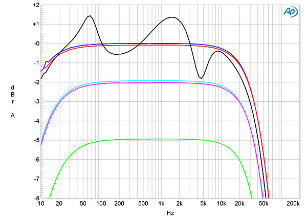
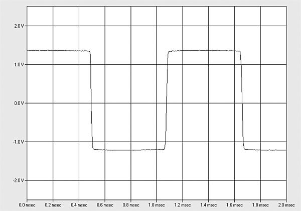
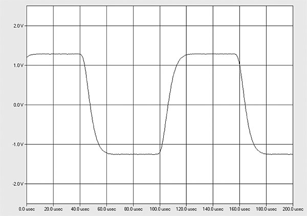
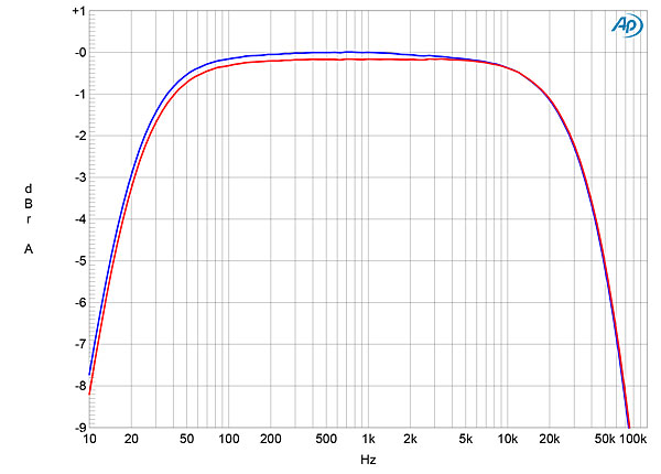
The headphone output's source impedance was a relatively high 113 ohms across the audioband, which won't be optimal for low-impedance headphones. The loudspeaker output impedance was a high 3.3 ohms at 20Hz, falling slightly to 2.57 ohms at 1kHz and 20kHz. The variation in the Western Electric amplifier's small-signal frequency response with our standard simulated loudspeaker (fig.1, gray trace) was ±1.4dB, which would be audible. Into resistive loads (fig.1, blue, red, cyan, magenta, and green traces), the VTA-70 started to roll off above 10kHz, reaching –3dB at 35kHz. Fig.1 was taken with the volume control set to its maximum; the excellent channel matching was preserved at lower settings of the control. The 91E's reproduction of a 1kHz squarewave into 8 ohms (fig.2) was superbly square. The ultrasonic rolloff lengthened the risetimes of a 10kHz squarewave (fig.3), though no overshoot or ringing is present.
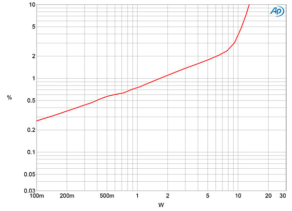
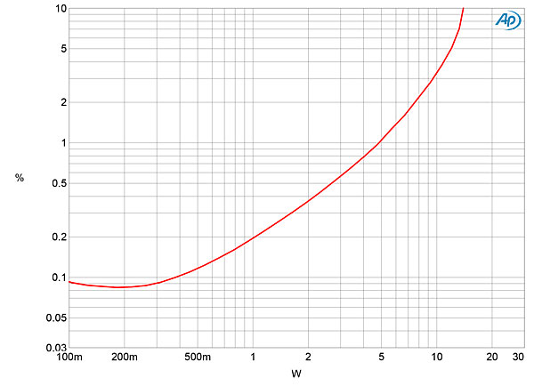
 Western Electric specifies the 91E's maximum power into 8 ohms as 20Wpc (15.44dBW) at 10% THD, 16Wpc (12dBW) at 5% THD, and 14Wpc (11.46dBW) at 3% THD (footnote 1). With our usual definition of clipping—when the THD+noise reaches 1%—and with both channels driven, I measured a clipping power of just 1.8Wpc into 8 ohms (2.55dBW, fig.5). At 3% THD+N, I measured 9.23Wpc (9.65dBW), and at 10%, 12.8Wpc (11dBW). Slightly more power was available into 4 ohms (fig.6): 4.8Wpc (3.8dBW) at 1% THD+N; 10Wpc (7dBW) at 3% THD+N; and 14Wpc (8.45dBW) at 10% THD+N. The shape of the traces in these graphs suggests that the amplifier uses a very limited amount of loop negative feedback.
 The input impedance was 42k ohms at 20Hz and 1kHz, 34.3k ohms at 20kHz (MM) and 993 ohms at 20Hz, 979 ohms at 1kHz, 968 ohms at 20kHz (MC). The phono input's RIAA error was very low, with very good channel matching (fig.12), though the low and high frequencies rolled off a little, reaching –1dB at 35Hz and 20kHz. Set to MM, the wideband, unweighted S/N ratio with the inputs shorted to ground and the volume control set to the maximum was a good 67dB (average of both channels), ref. 1kHz at 5mV. Restricting the measurement bandwidth to the audioband increased the ratio to 79.7dB, while an A-weighting filter further increased the ratio to 84.2dB. The S/N ratios in MC mode were 10–12dB lower, but this is still a relatively quiet phono stage.
 The Western Electric 91E is an intriguing mix of modern technology—the computer-optimized tube biasing, the precision volume control, the front-panel meters—and almost-century-old tube technology. Its measured performance is what I would expect from an amplifier with a single-ended output stage that uses a single 300B tube. Given its high levels of both harmonic and intermodulation distortion, even at lowish powers, it will work best with loudspeakers that have a 4 ohm nominal impedance and high sensitivity.—John Atkinson
Footnote 1: Kudos to Western Electric for reporting the THD level at which maximum output power is measured.—Jim Austin Footnote 2: I created tracks on Stereophile's Test CD 2 so listeners could hear at what percentage of second, third, or seventh harmonic they become aware of the distortion. See stereophile.com/content/istereophileis-test-cd-2-tracks-20-26.
Footnote 3: See fig.14 here.
Fig.1 Western Electric 91E, frequency response at 2.83V into: simulated loudspeaker load (gray), 8 ohms (left channel blue, right red), 4 ohms (left cyan, right magenta), and 2 ohms (green) (1dB/vertical div.).
Fig.2 Western Electric 91E, small-signal 1kHz squarewave into 8 ohms.
Fig.3 Western Electric 91E, small-signal 10kHz squarewave into 8 ohms.
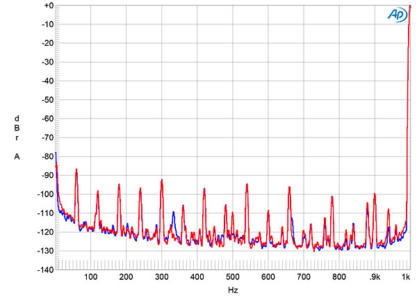
The 91E's channel separation (not shown) was >60dB in both directions below 2kHz but decreased to 40dB at 20kHz. The unweighted, wideband signal/noise ratio (ref.1W into 8 ohms), taken with the input shorted to ground and the volume control set to its maximum, was a good 79.7dB (average of the two channels). This ratio improved to 86.1dB when the measurement bandwidth was restricted to 22Hz–22kHz, and to 90.6dB when A-weighted. Spectral analysis of the low-frequency noisefloor while the Western Electric amplifier drove a 1kHz tone at 1Wpc into 8 ohms with the volume control set to maximum (fig.4, blue and red traces) revealed a low level of random noise, and the AC-related spuriae at 60Hz and its odd- and even-order harmonics lay at or below –90dB.
Fig.4 Western Electric 91E, spectrum of 1kHz sinewave, DC–1kHz, at 1Wpc into 8 ohms with volume control set to its maximum (left channel blue, right red) (linear frequency scale).
Fig.5 Western Electric 91E, distortion (%) vs 1kHz continuous output power into 8 ohms.
Fig.6 Western Electric 91E, distortion (%) vs 1kHz continuous output power into 4 ohms.
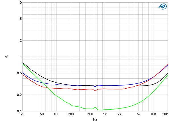
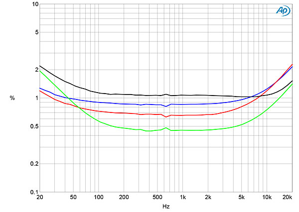
Fig.7 shows how the percentage of THD+N in both channels varied with frequency into 8 and 4 ohms at 1V. The THD+N rose slightly at the frequency extremes and was higher in the left channel into 8 ohms (blue trace) but in the right channel into 4 ohms (gray trace). At 2.83V, which is equivalent to 1W into 8 ohms (fig.8), the distortion was close to 1% in both channels.
Fig.7 Western Electric 91E, THD+N (%) vs frequency at 1V into: 8 ohms (left channel blue, right red), 4 ohms (left green, right gray).
Fig.8 Western Electric 91E, THD+N (%) vs frequency at 2.83V into: 8 ohms (left channel blue, right red), 4 ohms (left green, right gray).
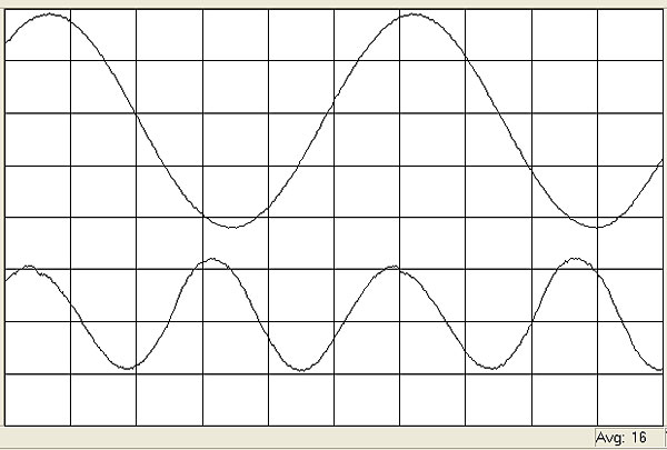
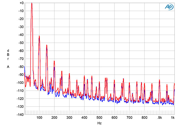
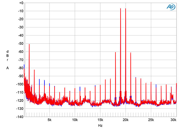
Fortunately, the distortion waveform (fig.9) was predominantly the subjectively innocuous second harmonic (footnote 2), at 0.8%. The third harmonic was also present, albeit at a lower level, especially into 4 ohms (fig.10). By themselves, the second and third harmonics may not result in audible distortion, even at relatively high levels. However, this will only be true if they are not accompanied by intermodulation distortion. With the 91E driving an equal mix of 19 and 20kHz tones at 1Wpc peak into 4 ohms (fig.11), the 1kHz difference product lay at –50dB (0.3%), with the higher-order products at 18 and 21kHz 10dB lower in level. These products were all 5dB higher in level at 1W into 8 ohms (not shown), which experience leads me to believe is marginal performance. It is fair to note, however, that this level of intermodulation is identical to that of the Air Tight ATM-300R power amplifier that Art Dudley favorably reviewed in February 2019 (footnote 3), which also used a single 300B tube for each channel's output.
Fig.9 Western Electric 91E, left channel, 1kHz waveform at 1W into 8 ohms, 0.8% THD+N (top); distortion and noise waveform with fundamental notched out (bottom, not to scale).
Fig.10 Western Electric 91E, spectrum of 50Hz sinewave, DC–1kHz, at 1Wpc into 4 ohms (left channel blue, right red; linear frequency scale).
Fig.11 Western Electric 91E, HF intermodulation spectrum, DC–30kHz, 19+20kHz at 1Wpc peak into 4 ohms (left channel blue, right red; linear frequency scale).
To examine the behavior of the Western Electric's phono input, I connected a wire from the Audio Precision's ground terminal to the grounding lug on the rear panel, to obtain the lowest noise. The phono input inverted absolute polarity at all the outputs. I measured a maximum gain at 1kHz at the loudspeaker outputs of 71.5dB (MM) and 82.1dB (MC). I performed all the subsequent testing using the headphone output and with the volume control set to –9.5dB, to avoid overloading the tubed output stage. (Inserting a plug into the headphone jack mutes the speaker outputs.) I repeated some of the testing at the preamplifier output.
Fig.12 Western Electric 91E, phono input, response with RIAA correction (left channel blue, right red) (1dB/vertical div.).
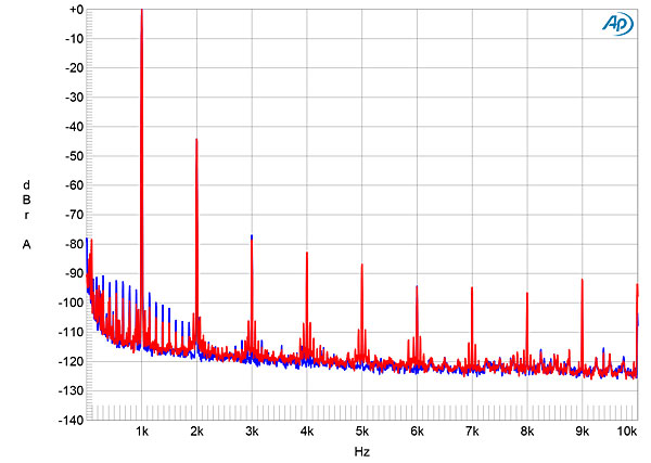
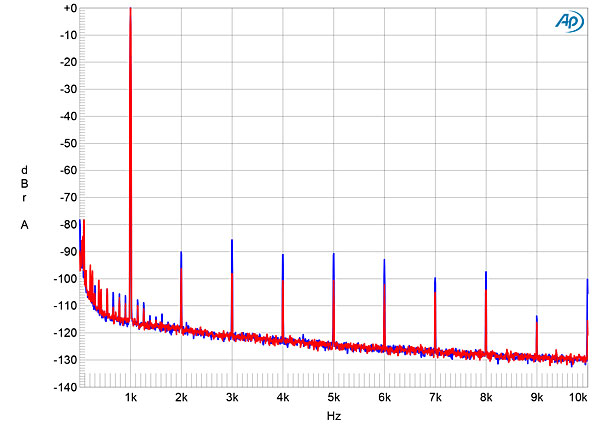
The phono input, measured at the headphone output, had high levels of distortion, with the second harmonic the highest in level at –44dB (0.6%, fig.13) with an input signal of 5mV. The harmonic distortion signature is very similar to that measured at the loudspeaker outputs, which makes me suspect that the headphone output is derived from the single-ended tubed output stage, most likely with a series resistor. I therefore repeated the spectral analysis at the preamplifier output (fig.14). Though high-order harmonics are visible, these all lie at or below –90dB (0.003%), and the second harmonic is now almost 50dB lower than it had been from the headphone output.
Fig.13 Western Electric 91E, MM phono input, spectrum of 1kHz sinewave, DC–10kHz, for 5mV input, measured at headphone output (left channel blue, right red, linear frequency scale).
Fig.14 Western Electric 91E, MM phono input, spectrum of 1kHz sinewave, DC–10kHz, for 5mV input, measured at Preamplifier output (left channel blue, right red, linear frequency scale).
The high level of second harmonic distortion present in the headphone output affected the overload margin measurements. In MM mode, the margins, calculated from the difference between the nominal 1kHz input level of 5mV and the input voltage where the THD+N reached 1%, were disappointing, at 3.4dB at 20Hz, 4.2dB at 1kHz, and –8.4dB at 20kHz. The margins in MC mode, ref. 1kHz at 0.5mV, were all 0.5dB lower. However, repeating the overload margin measurements at the preamplifier output gave an 8dB improvement at 20Hz and 1kHz in both MM and MC mode, though the margins at 20kHz were still low.
Footnote 1: Kudos to Western Electric for reporting the THD level at which maximum output power is measured.—Jim Austin Footnote 2: I created tracks on Stereophile's Test CD 2 so listeners could hear at what percentage of second, third, or seventh harmonic they become aware of the distortion. See stereophile.com/content/istereophileis-test-cd-2-tracks-20-26.


