To examine the phono input's performance, I connected a wire from the grounding terminal on the amplifier's rear panel to the analyzer's chassis ground to minimize noise. To avoid overdriving the tubed output stage, I mostly did this testing by looking at the headphone output. (The manual says that inserting a plug into the headphone jack turns off the speaker outputs, but I found that rather than muting them completely, it reduced their level by 44dB.)
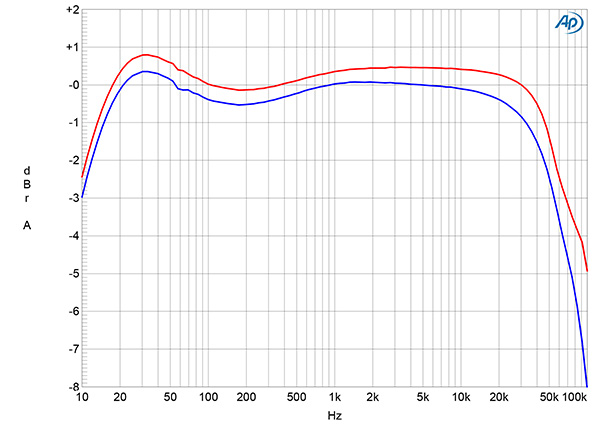
The phono input preserved absolute polarity at all three output types. The maximum gain was 69.9dB from the 8 ohm output transformer tap into 8 ohms, 68.4dB from the 4–6 ohm output transformer tap into 8 ohms, and 60.1dB from the headphone output. The input impedance, specified as 47k ohms, was 45k ohms at 20Hz and 1kHz, 39.4k ohms at 20kHz. The HFSA-01's RIAA equalization (fig.12) featured a slight lack of lower midrange energy and a small boost in the low bass before rolling off to reach –3dB at 10Hz. Note the 0.4dB channel imbalance in this graph; the volume control was set to 11:00 when I made this measurement.
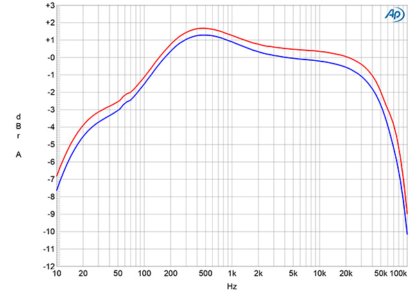

Aurorasound supplies an overlay that fits over the treble and bass controls on the front panel and shows the tone control settings that are appropriate for different record equalizations. Figs.14 and 15 respectively show the differences made to the RIAA response by setting the controls to "Columbia" and "Decca." (Note the different vertical scale compared with fig.13.)
Channel separation (not shown) was 60–70dB in both directions across the audioband. With the phono inputs shorted to ground and the volume control set to the maximum, the Aurorasound phono input's unweighted, wideband S/N ratio, measured at the headphone output and ref. 1kHz at 5mV, was a good 75dB in the left channel and a better 82.2dB in the right. Restricting the measurement bandwidth to 22Hz–22kHz slightly increased these ratios, while inserting an A-weighting filter improved them to an excellent 91.9dB, left, and 89.1dB, right.
To examine the HFSA-01 phono input's overload margins, I reduced the volume control setting by 30dB, to ensure I was looking at true input overload rather than clipping at the headphone output. The margin ref. 1kHz at the standard moving magnet level of 5mV was a superb 27.2dB at 20Hz and 1kHz and still 25.8dB at 20kHz.
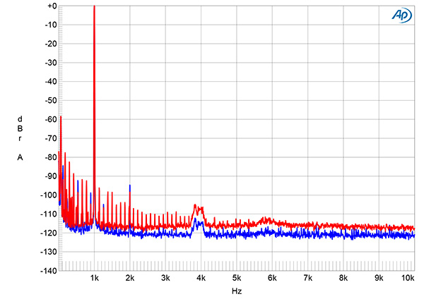
The phono input offered very low distortion. Fig.16 shows the spectrum at the headphone output with a 1kHz input signal at 20mV, 12dB above the standard MM input level. The only distortion harmonic that can be seen above the noisefloor is the second, at –96dB (0.0015%). Intermodulation distortion was similarly low (not shown).
The Aurorasound HFSA-01's measured performance is what I would expect from a design with a tubed output stage and little loop negative feedback. While the amplifier only meets its specified power at close to 10% THD+N, the distortion is predominantly the subjectively innocuous second and third harmonics and is very low at moderate powers. The best performance is obtained from the 4 ohm output transformer tap, the 8 ohm tap not being able to maintain its linearity into loads below 8 ohms. The phono input offers low noise and high overload margins.—John Atkinson


