Sidebar 3: Measurements
The Accuphase DG-68 is a complicated product, comprising an analog–digital converter (ADC), digital signal processing (DSP), and a digital–analog converter (DAC). It also has digital inputs and outputs that bypass the ADC and DAC stages. JVS used it as a complete analog–analog processor, so, in addition to examining the individual performance of the ADC, DSP, and DAC stages, I looked at its behavior as set by JVS.
I used my Audio Precision SYS2722 system (see the January 2008 "As We See It") to perform the measurements, repeating some tests with the magazine's more-recent APx555 system. While Accuphase specifies the coaxial S/PDIF input as accepting data sampled at rates up 192kHz, it wouldn't lock at rates greater than 96kHz to the coaxial digital output of either Audio Precision system. The optical S/PDIF input accepted sample rates up to 96kHz, as specified.
Looking first at the DG-68's performance as a D/A processor, the maximum output level at 1kHz with its Automatic Level Control switched on was 1.7V from both the balanced and single-ended outputs. With its rear-panel switch set to pin 2 of the output XLR's positive, the Accuphase preserved absolute polarity (ie, was noninverting) from both sets of analog outputs. The output impedance was a low 47 ohms from both outputs at 20kHz and 1kHz, rising to a still-low 83 ohms (balanced) and 66 ohms (unbalanced) at 20Hz.
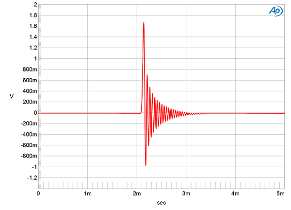
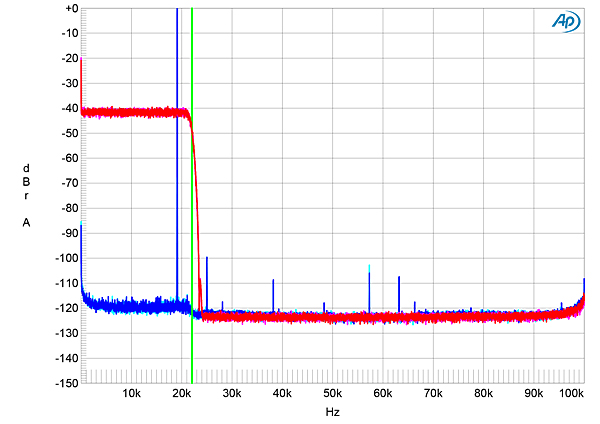
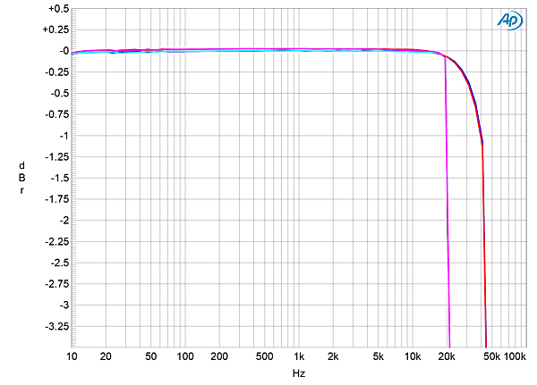
The Accuphase's DAC offers a single reconstruction filter with a classic minimum-phase response (fig.1), all ringing following the single high sample. This filter's ultrasonic rolloff with 44.1kHz data (fig.2, magenta and red traces) reaches full stop-band attenuation just above half the sample rate (the vertical green line). The aliased image at 25kHz of a full-scale tone at 19.1kHz (cyan, blue) is suppressed by 100dB, and the harmonics associated with the 19.1kHz tone are all very low in level. Fig.3, taken with digital data sampled at 44.1kHz and 96kHz, shows that the D/A response rolls off sharply just below half the sample rate.
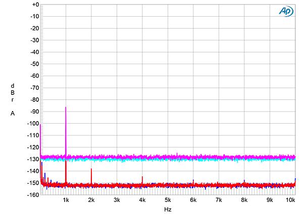
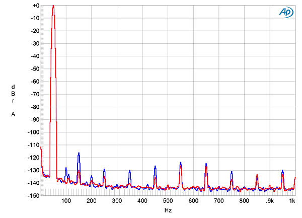
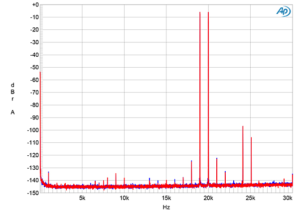
 As a DAC, the Accuphase produced very low levels of harmonic distortion with full-scale digital data; the second harmonic was higher in the left channel (fig.8, blue trace) than the right (red trace). However, at just –117dB (0.00014%), this is inconsequential. This spectrum was taken with dithered 24-bit data into a high 100k ohm load. When I reduced the load impedance to the current-hungry 600 ohms, the distortion spectrum hardly changed. Intermodulation distortion with an equal mix of 19 and 20kHz tones, each lying at –6dBFS, was similarly very low (fig.9), with the difference tone at 1kHz lying at –134dB (0.00005%). The aliased images of the primary tones can be seen in this graph, but they lie at –99dB and –107dB. Again, substituting 600 ohms for 100k ohms hardly changed the level of the intermodulation products.
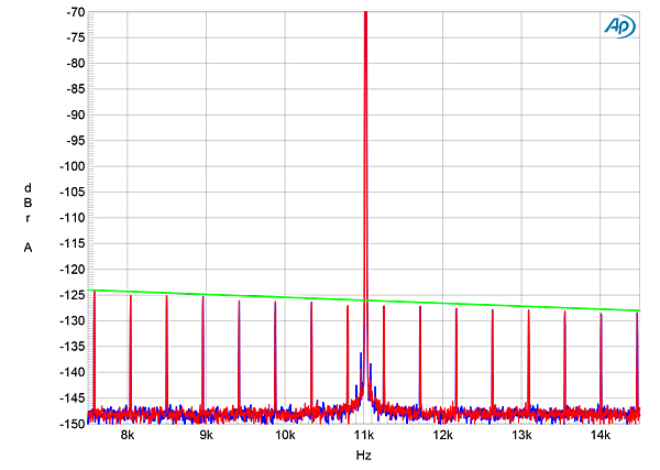
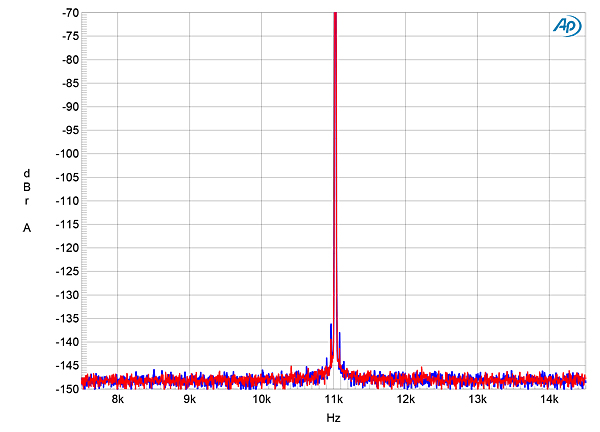
 When I examined the Accuphase's rejection of word-clock jitter via its S/ PDIF inputs with 16-bit J-Test data, it did very well (fig.10). All the odd-order harmonics of the undithered low-frequency LSB-level squarewave lie at the correct levels, indicated by the sloping green line, and while power supply–related sidebands can be seen at 60Hz and 120Hz on either side of the high-level tone at one-quarter the sample rate, these can only be seen because of the very low noise floor offered by the DG-68's analog output. Repeating the test with 24-bit data gave a clean spectrum (fig.11).
 Turning to the DG-68's A/D coverter, I examined its performance in the digital domain by connecting its coaxial digital output to the SYS2722's digital input. The sample rate can be set to 44.1kHz, 88.2kHz, 176.4kHz, or 352.8kHz. I mainly performed the ADC measurements at 88.2kHz. The unbalanced analog input impedance was 19.5k ohms at 20Hz and 1kHz, dropping to 10k ohms at 20kHz. The balanced input impedance was twice the unbalanced, as expected.
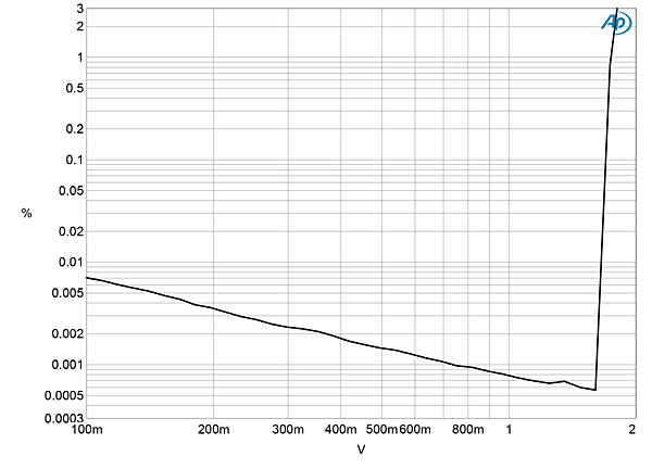
Accuphase's specifications say that the analog input clips at 1.78V with the gain set to "0dB." I found that the analog input clips (when the THD+noise reaches 1%) at 1.85V (fig.12). When you clip the analog input, the word "Peak" lights up in red in the display and you need to reduce the input sensitivity with the control panel.
Turning to the DG-68's A/D coverter, I examined its performance in the digital domain by connecting its coaxial digital output to the SYS2722's digital input. The sample rate can be set to 44.1kHz, 88.2kHz, 176.4kHz, or 352.8kHz. I mainly performed the ADC measurements at 88.2kHz. The unbalanced analog input impedance was 19.5k ohms at 20Hz and 1kHz, dropping to 10k ohms at 20kHz. The balanced input impedance was twice the unbalanced, as expected.
Accuphase's specifications say that the analog input clips at 1.78V with the gain set to "0dB." I found that the analog input clips (when the THD+noise reaches 1%) at 1.85V (fig.12). When you clip the analog input, the word "Peak" lights up in red in the display and you need to reduce the input sensitivity with the control panel.
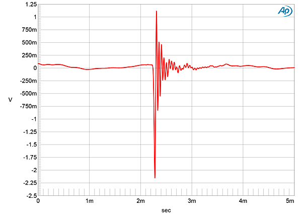
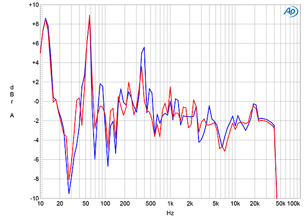
 Finally, I examined the effect of the DG-68's DSP, with the settings that had been created by JVS, by switching on "VC/EQ." Fig.16 shows the effect on the impulse response. As expected, the equalization's digital filters have modified the impulse response. (A digital filter operates by multiplying or "convolving" the input data with its own impulse response.) The result in the frequency domain of JVS's preferred settings (without smoothing) is shown in fig.17; it reveals the DG-68's versatility—the "Voicing" IIR filter has 67 1/6-octave bands, the "Equalizer" IIR filter has 80 bands, all offering ±12dB adjustments. (The DG-68's spectrum analyzer screen echoes traditional analog analyzers in that pink noise appears flat.) Significantly, switching in the equalization did not reduce resolution or increase distortion.
 The Accuphase DG-68's measured performance indicates that no compromises have been made to achieve its versatility.—John Atkinson
Fig.1 Accuphase DG-68, DAC mode, impulse response (one sample at 0dBFS, 44.1kHz sampling, 5ms time window).
Fig.2 Accuphase DG-68, DAC mode, wideband spectrum of white noise at –4dBFS (left channel red, right magenta) and 19.1kHz tone at 0dBFS (left blue, right cyan) into 100k ohms with data sampled at 44.1kHz (20dB/vertical div.).
Fig.3 Accuphase DG-68, DAC mode, frequency response at –12dBFS into 100k ohms with data sampled at: 44.1kHz (left channel cyan, right magenta) and 96kHz (left blue, right red) (0.5dB/vertical div.).
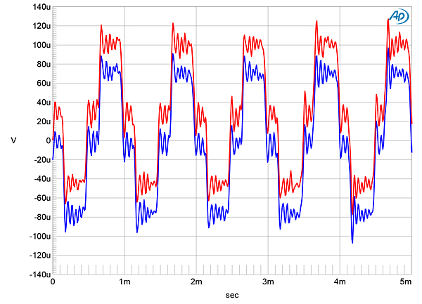
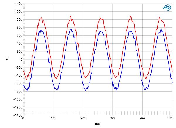
Channel separation was superb, at>126dB in both directions below 1kHz, decreasing to a still-superb 112dB at 20kHz. The DG-68's analog noise floor was very low and free from power supply–related spuriae (fig.4). An increase in bit depth from 16 to 24, with dithered data representing a 1kHz tone at –90dBFS, dropped the Accuphase's noise floor by 21dB (fig.5), which implies a resolution between 19 and 20 bits. When I played undithered data representing a tone at exactly –90.31dBFS, the waveform was symmetrical, with the three DC voltage levels described by the data free from noise (fig.6). A very slight DC offset of +25µV was present in the right channel's output. With undithered 24-bit data (fig.7), the Accuphase's very low analog noise floor allowed it to output a clean sinewave, even at this very low signal level.
Fig.4 Accuphase DG-68, DAC mode, spectrum with noise and spuriae of dithered 1kHz tone at 0dBFS with 24-bit TosLink data (left channel blue, right red) (10dB/vertical div.).
Fig.5 Accuphase DG-68, DAC mode, spectrum with noise and spuriae of dithered 1kHz tone at –90dBFS with: 16-bit data (left channel cyan, right magenta), 24-bit data (left blue, right red) (20dB/vertical div.).
Fig.6 Accuphase DG-68, DAC mode, waveform of undithered 1kHz sinewave at –90.31dBFS, 16-bit data (left channel blue, right red).
Fig.7 Accuphase DG-68, DAC mode, waveform of undithered 1kHz sinewave at –90.31dBFS, 24-bit data (left channel blue, right red).
Fig.8 Accuphase DG-68, DAC mode, spectrum of 50Hz sinewave, DC–1kHz, at 0dBFS into 100k ohms (left channel blue, right red; linear frequency scale).
Fig.9 Accuphase DG-68, DAC mode, HF intermodulation spectrum, DC–30kHz, 19+20kHz at 0dBFS into 100k ohms, 44.1kHz data (left channel blue, right red; linear frequency scale).
Fig.10 Accuphase DG-68, DAC mode, high-resolution jitter spectrum of analog output signal, 11.025kHz at –6dBFS, sampled at 44.1kHz with LSB toggled at 229Hz: 16-bit TosLink data (left channel blue, right red). Center frequency of trace, 11.025kHz; frequency range, ±3.5kHz.
Fig.11 Accuphase DG-68, DAC mode, high-resolution jitter spectrum of analog output signal, 11.025kHz at –6dBFS, sampled at 44.1kHz with LSB toggled at 229Hz: 24-bit TosLink data (left channel blue, right red). Center frequency of trace, 11.025kHz; frequency range, ±3.5kHz.
Fig.12 Accuphase DG-68, ADC mode, THD+noise (%) vs input level in volts.
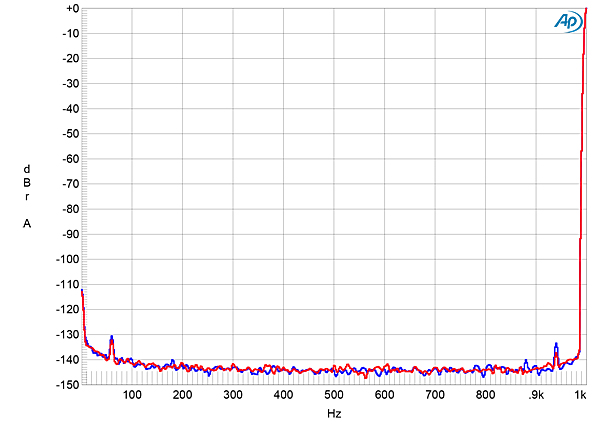
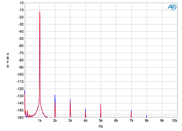
At levels lower than 1.85V, the DG-68 digitizes its analog inputs with very low distortion. Fig.13, for example, shows a spectral analysis of the Accuphase's digital output with an analog signal 3dB below clipping. While some distortion harmonics can be seen, these are vanishingly low in level. The second harmonic is the highest, but at –129dB, left, and –140dB, right, it is insignificant. Note the circa 15dB of headroom visible in this graph. This is to allow the DG-68's equalization to apply up to 12dB gain without the level exceeding 0dBFS.
Fig.13 Accuphase DG-68, ADC mode, digital-domain spectrum of 1kHz sinewave, DC–10kHz, at –3dB ref clipping voltage (left channel blue, right red; linear frequency scale). .
I then examined the DG-68's behavior from analog input to analog output with the DSP equalization bypassed. With the Automatic Level Control (ALC) active, a 1kHz analog input signal at 1V resulted in an analog output level of 949mV, ie, an insertion loss of just 0.23dB. I switched ALC off, which set the output level to "0.0dB," and adjusted the level with the input gain adjust buttons on the remote control: "–6dB" gave an analog output level of 1.341V, ie, a gain of 3dB compared with ALC on; "0dB" resulted in an analog output signal of 2.674V; "5dB" resulted in 4.756V (exactly +5dB); but higher gain settings clipped the output.
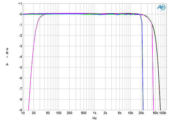
Fig.14 shows the frequency response at all four ADC sample rates, with and without the subsonic filter active. The response at 352.8kHz (blue and red traces) is identical to that at 176.4kHz (green and gray traces), with a rolloff reaching –3dB at 55kHz. (The specifications say the –3dB frequency is 50kHz.) The subsonic filter offers a sharp rolloff below 40Hz, reaching –3dB at 20Hz. Some slight passband ripple can be seen, this presumably due to the ADC's antialiasing filter.
Fig.14 Accuphase DG-68, analog input–analog output mode with and without subsonic filter, frequency response at 1V into 100k ohms with data sampled at: 44.1kHz (left channel blue, right cyan). 88.2kHz left cyan, right magenta), 176.4kHz (left green, right gray), and 384kHz (left blue, right red) (1dB/vertical div.)
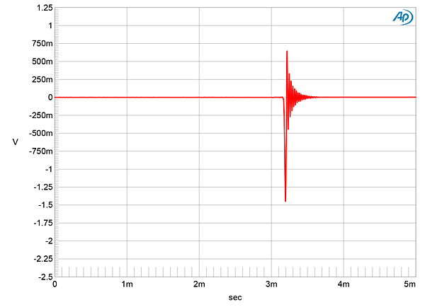
I examined the DG-68's impulse response from its analog input to analog output by using the shaped impulse sampled at 384kHz I used for my 2019 ADC article. I played this file with the Pure Music 3.0 app on my MacBook Pro, sending the impulse data to a Mytek HiFi Brooklyn DAC via USB. As the signal's sample rate was 384kHz and I was testing the Accuphase with its sample rate set to 88.2Hz, the ringing of the Brooklyn's own reconstruction filter at 192kHz would be two octaves above the DG-68 ADC's Nyquist frequency and would not affect the result. Fig.15 shows the result with the equalization bypassed. Other than the doubled sample rate, the impulse response is the same minimum-phase type seen in fig.1. However, it is now inverted: The balanced input XLR jacks are permanently wired with pin 3 positive, the opposite to how the output XLR jacks had been set. The unbalanced analog inputs preserved absolute polarity.
Fig.15 Accuphase DG-68, analog input–analog output mode, impulse response (one sample at 0dBFS, 88.2kHz sampling, 5ms time window).
Fig.16 Accuphase DG-68, analog input–analog output mode with VC/EQ active, impulse response (one sample at 0dBFS, 88.2kHz sampling, 5ms time window).
Fig.17 Accuphase DG-68, analog input–analog output mode with VC/EQ active, 88.2kHz sampling, frequency response at 1V into 100k ohms (left channel blue, right red) (2dB/vertical div.)