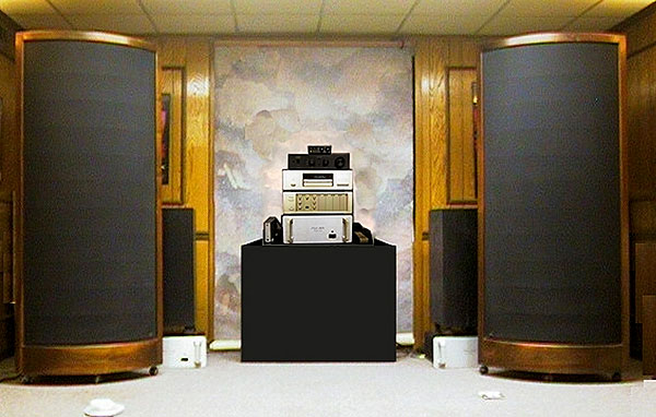
The Model A-1 represents Sound-Lab's best effort at designing a system that appears to have a curved diaphragm. A truly curved diaphragm (à la MartinLogan) can have wide horizontal sound dispersion, but the problem is its limited linearity at low frequencies, where large excursions are required. When the diaphragm is pulled forward, it is stretched, increasing tension. When pulled back, its arc of curvature decreases, which causes it to lose tension. This difference in tension in the two halves of a push-pull cycle severely limits the linear excursion range where distortion will be low. What's a poor designer to do?
Rather than use a diaphragm that is actually curved in the horizontal plane, Sound-Lab opted to use an array, or mosaic, of small, flat-diaphragmed transducer cells. In such an array, a large sheet of Mylar is stretched over a rigid frame which subdivides the sheet into an array of flat cells. The diaphragm is locked onto the outer edges of the frame with a compound precision-molded clamp that assures no slippage of diaphragm tension over time. The cells are then arranged to form several long vertical facets positioned to approximate a curved surface. Sound-Lab's flat diaphragm ensures symmetrical behavior as it moves between the stators. Care is taken to keep the dead zone between facets down to 1/32". Further, to prevent an acoustic "venetian-blind" effect, the angle between adjacent facets is chosen so that the facets should integrate smoothly in the horizontal plane without lobes in the pressure response.
Any taut, underdamped membrane (eg, a drumhead) exhibits a significant fundamental resonance. Such drumhead resonances are undesirable in a speaker; the large peak (most often in the midbass) not only colors the sound, but also limits the speaker's usable dynamic range. The diaphragm can slap the stator electrodes and make nasty crunching sounds that sound little like music. Something must be done to control this resonance. Normally, resistive damping in the form of a cloth mesh or foam placed next to the stators controls diaphragm motion and reduces the Q of the resonance.
Sound-Lab's inventive approach, dubbed the "distributed bass resonance" principle, is protected under US patent. In this design, the diaphragm is physically subdivided into sectors in such a way as to stagger the sectors' resonance frequencies, spreading the bass resonance energy over a greater frequency range. As a result, the Q of the resonance is reduced, but as an added benefit, bass extension is improved. In the loudspeaker's nearfield, the bass response rises at a rate of about 6dB/octave, just enough to compensate for front-to-back dipole cancellation of bass energy for an octave or so below the diaphragm's drumhead resonant frequency. Farther into the room, in the far field, say 10' from the loudspeaker, the back wave wraps around the panel and neatly wipes out the array's inherent rising bass response. The result is a flatter, deeper bass response, marred only by the presence of the ubiquitous room modes.
The interface electronics package is housed in the speaker's base. An ultrasonic type of bias power supply is used, said to eliminate the power-line noise and hum typical of 50/60Hz supplies. A pair of step-up transformers is used to cover the audio spectrum. One transformer (actually two transformers connected in parallel) is primarily dedicated to the bass frequencies, while the other handles the upper range. The transformers overlap in the lower midrange. The interface was redesigned in Fall 1991 to improve the integration between the transformers and to increase the core saturation headroom. Better passive parts are also used. I can tell you from my own listening that an upgrade to the new interface is well worth the expense. Tonal balance in the lower midrange improved, as did midrange transparency. A similar interface upgrade is also available for the Sound-Lab A-3.
Three adjustment controls are provided on the back plate. The Brilliance control pot adjusts the treble level, the maximum position yielding the maximum high-treble sensitivity, counterclockwise rotation reducing the treble response. This control should be adjusted by ear, the optimum setting being a function of listening-room damping and front-end balance.
Control is also provided over the bass response, which can be shelved in 3dB steps relative to the midrange and treble. From the nominal 0dB bass setting, adjustments to +3dB, –3dB, and –6dB are possible by moving a jumper. If you're a bass hog, you might find heaven at the +3dB position. But for most of us, the goal should be to contour the tonal balance so that the bass response at the listening seat sounds right.
Finally, the Bias control allows adjustment of the DC bias voltage to the diaphragm. Think of it as a speaker sensitivity control: the higher the bias voltage, the more sensitive the speaker. That's good; the amplifier headroom requirements are lessened. Because the electrostatic array is tested at much higher voltages than those available at any bias control setting, it's perfectly safe to crank this control fully clockwise for maximum bias voltage. When you do, you'll very likely encounter crackling noise. That's normal, and is indicative of minor static discharges between the diaphragm and stators. Simply back up the Bias control until the crackling stops. After several hours of break-in, it may be possible to advance the pot to a higher bias setting. The ultimate bias setting achievable is a function of the local altitude and humidity. My listening room is 6800' above sea level; after six months, I'm still sitting pretty close to the minimum bias level.
Input connections are via five-way binding posts of average quality: a plastic body with a gold-plated metal core. C'mon, Roger—these speakers deserve much better connectors. WBTs would have been nice.
Planar power
Imagine a cylinder nearly 6' tall with a radius of 19.6". Slice the cylinder into equal quarters, as you might a pie. One of these quarters represents the A-1's radiation pattern. Thus, the A-1's horizontal dispersion is a full 90°; that of its smaller brother, the Model A-3, is only 75° (footnote 1).
Footnote 1: The A-3 was reviewed by J. Gordon Holt in Vol.9 No.6, with "Follow-Ups" in Vol.11 Nos.6 & 11 and Vol.15 No.1.—John Atkinson