I measured the Meridian Explorer2 with my Audio Precision SYS2722 system (see the January 2008 "As We See It"). Source materials were WAV and AIFF test-tone files, played with Pure Music 3.0 on my MacBook Pro running on battery power. As with the original Explorer, I performed a complete set of measurements from both the line-level and headphone outputs, but most of what I describe here is the Explorer's performance from its line output; I comment on the headphone output only when it differed. I also comment on the Explorer2's measurements only when they differ from the original Explorer's. (You can find the original measurements here.)
The maximum output level at 1kHz was very similar to the original's, at 2.12V from the line output and 1.85V from the headphone jack, the latter taken with the computer's volume control set to –4dB to avoid waveform clipping. While the line output preserved absolute polarity (ie, was non-inverting), the headphone output inverted absolute polarity. Like the first Explorer, the line output impedance was a fairly high 465 ohms at low and middle frequencies, dropping slightly to 456 ohms at the top of the audioband, which is why this jack should not be used to drive headphones. As claimed by Meridian, the headphone output impedance was lower than the original's, at <1 ohm at all audio frequencies.
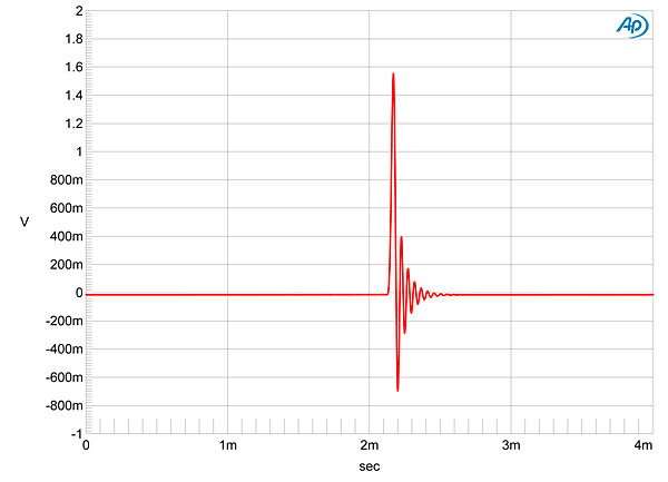
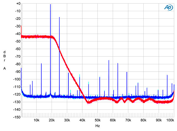
The original Explorer's impulse response with 44.1kHz data (fig.1) reveals the reconstruction filter to be a minimum-phase type, with all the ringing occurring after the impulse. The new version's impulse response (fig.2) is also typical of a minimum-phase low-pass filter, but with fewer coefficients than the original's. The red and magenta traces in fig.3, taken with 44.1kHz-sampled white noise, reveal the filter to roll off sharply above the baseband (footnote 1). The new sample's reconstruction filter, however, has a much slower rolloff, with its first null at the sample rate of 44.1kHz (fig.4, red and magenta traces), which means that the 25kHz aliasing product of a 44.1kHz-sampled tone at 19.1kHz (fig.4, blue and cyan traces) is suppressed by only 16dB compared with the 55dB of the original Explorer (fig.3, blue and cyan traces). Note, by the way, that I reduced the signal levels used to produce fig.4 by 1dB compared with those in fig.3. This is because the Explorer2's line output was beginning to clip with the 19.1kHz tone at 0dBFS (but not with a 1Hz tone at 0dBFS).


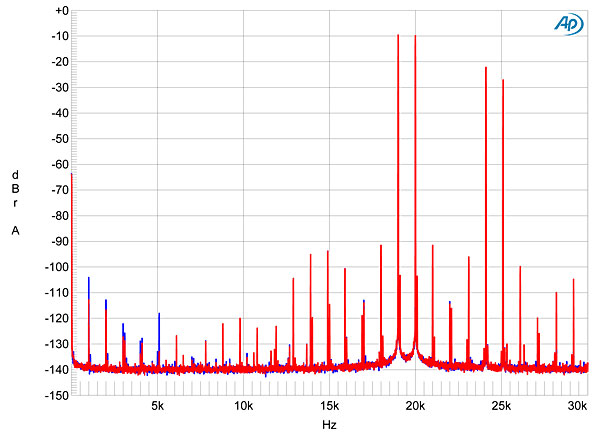
For the same reason, I tested for high-frequency intermodulation (fig.5) with the combined waveform with an equal-level pair of tones at 19 and 20kHz peaking at –3dBFS rather than 0dBFS. The Explorer shows only mild rejection of the imaging products at 24.1 and 25.1kHz, though actual intermodulation products are low in level. It looks as if the Explorer2 sacrifices a little bit of linearity with the rare, full-scale, high-frequency signals in order to maximize resolution, presumably to optimize its dynamic range window for MQA playback (footnote 2).
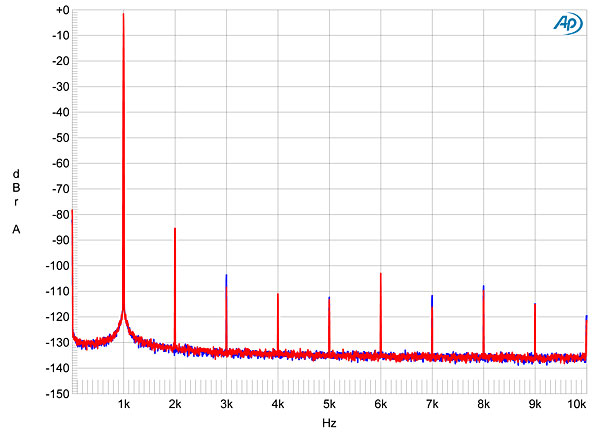
I mentioned earlier that the Explorer2's headphone output clipped with settings of the host computer's volume control greater than –4dB. That was into a high load impedance of 100k ohms. Tested into a lower load of 300 ohms, the Explorer2's headphone output is on the verge of clipping at that level, revealed by the picket fence of high-order harmonics (fig.6). Reducing the signal level by 2dB, which is still much higher than the volume control would be used in practice, eliminated almost all the higher-order harmonics, and the second harmonic is now the highest in level at a low –80dB (0.01%, fig.7).

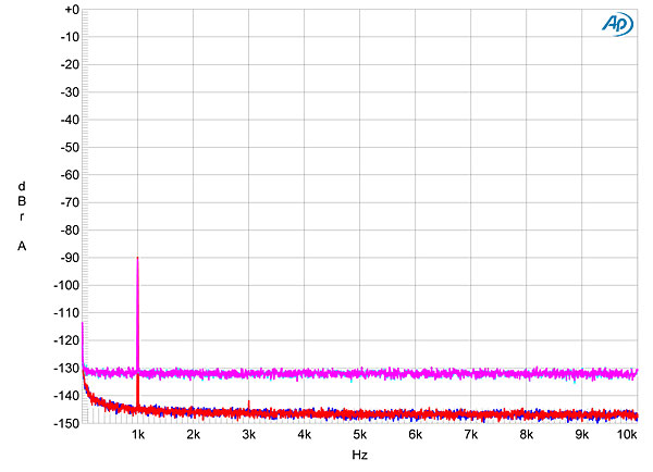
As with the original Explorer, the Explorer2 offers superb resolution, as it should given the need to be able to decode high-resolution MQA files. The traces in fig.8 were taken with dithered data representing a 1kHz tone with word lengths of 16 bits (cyan, magenta traces) and 24 bits (blue, red). The spectral line at 1kHz peaks at exactly –90dBFS, implying minimal linearity error. The 16-bit noise floor in this graph is actually the spectrum of the dither used to encode the data. With 24-bit data, the noise floor drops by 16dB or so, suggesting resolution approaching 19 bits—which is excellent, considering that the Explorer2 is powered by the host computer's 5V USB bus.
Like its predecessor, Meridian's Explorer2 offers superb measured performance.—John Atkinson
Footnote 1 My thanks to Jürgen Reis, of MBL, for suggesting this test to me.
Footnote 2: Bob Stuart commented that my conjecture that to avoid overload the maximum input at 19.1kHz was –1dBFS was correct. The design of the upsampling filter assumes reasonable music statistics, and its feed to the DAC cannot exceed full scale.