Sidebar 3: Measurements
I performed a complete set of measurements on one of the JMF HQS 7001s (serial number 311732) with my Audio Precision SYS2722 system, then repeated some of the testing with the magazine's APx500 analyzer. I preconditioned the HQS 7001 by following the CEA's recommendation of running it at one-eighth the specified power into 8 ohms for 30 minutes. At the end of that time, the temperature of the top panel was 101.8°F (38.8°C) and that of the heatsink on the rear panel was much higher, at 173.5°F (78.6.1°C). The JMF amplifier has just enough thermal capacity for its rated power.
The JMF amplifier's balanced input preserved absolute polarity, ie, the XLR jack was wired with pin 2 positive. The HQS 7001's input impedance is specified as 20k ohms. I measured 6.8k ohms from 20Hz to 20kHz. Though this is lower than the specified impedance, modern solid state preamplifiers will have no problems driving the JMF. The voltage gain at 1kHz was higher than usual, at 34.4dB into 8 ohms.
Footnote 1: See fig.3 here.
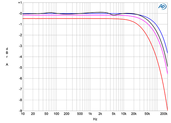
Fig.1 JMF HQS 7001, frequency response at 2.83V into: simulated loudspeaker load (gray), 8 ohms (blue), 4 ohms (magenta), and 2 ohms (red) (1dB/vertical div.).
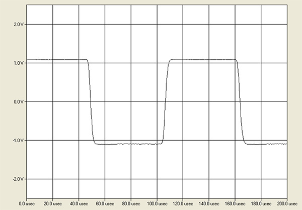
Fig.2 JMF HQS 7001, small-signal 10kHz squarewave into 8 ohms.
The output impedance, including the series impedance of 6' of spaced-pair cable, was a relatively low 0.15 ohms at 20Hz and 1kHz, rising to 0.23 ohms at 20kHz. As a result, the variation in the frequency response with our standard simulated loudspeaker (fig.1, gray trace) was minimal, at ±0.15dB. The response into resistive loads was flat in the audioband, not reaching –3dB until 180kHz into 8 ohms (blue trace) and 123kHz into 4 ohms (magenta). The rise in output impedance with increasing frequency means that into 2 ohms, the output was down by 3dB at 70kHz. With its wide small-signal bandwidth, the JMF's reproduction of a 10kHz squarewave into 8 ohms featured short risetimes in both modes (fig.2), with no overshoot or ringing.
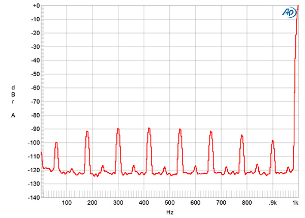
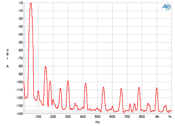
Fig.3 JMF HQS 7001, spectrum of 1kHz sinewave, DC–1kHz, at 1W into 8 ohms (linear frequency scale).
The unweighted, wideband signal/noise ratio (ref. 1W into 8 ohms), taken with the input shorted to ground, was a good 64.6dB. This ratio improved to 80.8dB when the measurement bandwidth was restricted to 22Hz–22kHz, and to 82.7dB when A-weighted. Spectral analysis of the low-frequency noisefloor while the JMF drove a 1kHz tone at 1W into 8 ohms (fig.3) revealed a low level of random noise, but spuriae were present at 60Hz and its odd-order harmonics, each close to –90dB ref. 1W. These will be due to magnetic interference from the power transformer.
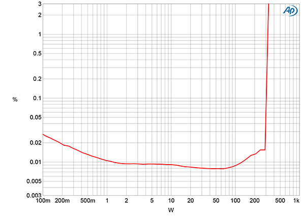
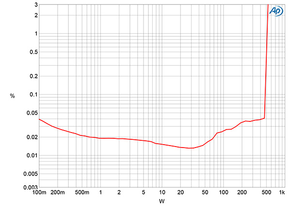
Fig.4 JMF HQS 7001, distortion (%) vs 1kHz continuous output power into 8 ohms.
Fig.5 JMF HQS 7001, distortion (%) vs 1kHz continuous output power into 4 ohms.
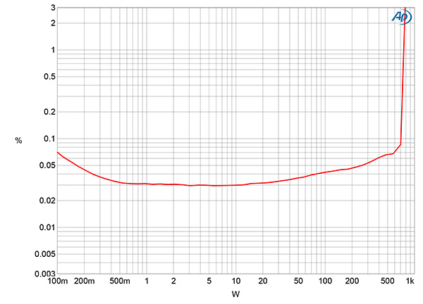
Fig.6 JMF HQS 7001, distortion (%) vs 1kHz continuous output power into 2 ohms.
JMF specifies the HQS 7001's maximum power as 300W into 8 ohms (24.77dBW), 500W into 4 ohms (24.0dBW), and 850W into 2 ohms (23.27dBW). Stereophile defines an amplifier's clipping power as being when the THD+noise reaches 1%. With that criterion, the HQS 7001 slightly exceeded its specified powers into 8 ohms (310W, 24.91dBW, fig.4), and into 4 ohms (515W, 24.1dBW, fig.5). The HQS 7001 clipped at 760W into 2 ohms (22.8dBW, fig.6), which is lower than the specified maximum power. However, the wall voltage had dropped from 121.4V AC with the amplifier idling to 118.7V AC with it clipping into 2 ohms; this drop was responsible for the shortfall in clipping power.
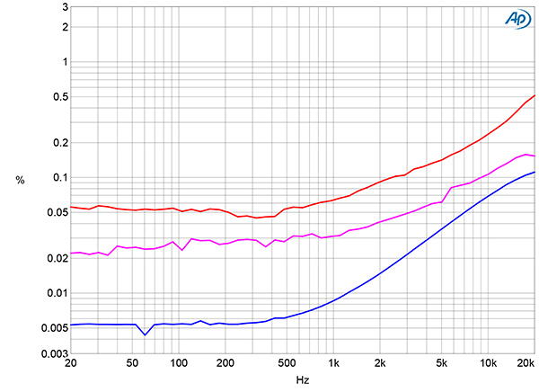
Fig.7 JMF HQS 7001, THD+N (%) vs frequency at 20V into: 8 ohms (blue), 4 ohms (magenta), and 2 ohms (red).
I examined how the THD+N percentage varied with frequency at 20V, which is equivalent to 50W into 8 ohms, 100W into 4 ohms, and 200W into 2 ohms. The THD+N percentage was low into 8 ohms (fig.7, blue trace) but rose into 4 ohms (magenta trace) and 2 ohms (red trace). The rise in THD+N in the top three audio octaves will be due to the amplifier having relatively limited open-loop gain, which means that less distortion-reducing feedback is available as the frequency rises (footnote 1).
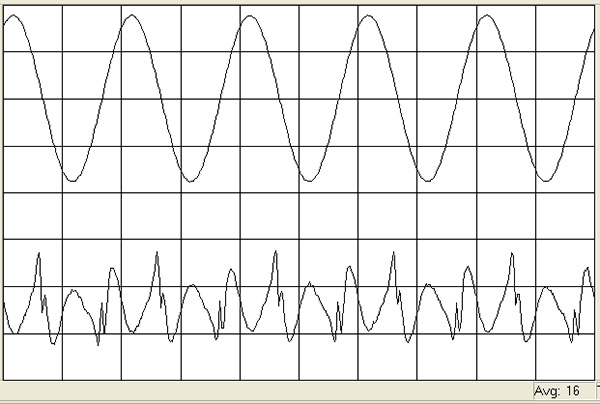
Fig.8 JMF HQS 7001, 1kHz waveform at 50W into 8 ohms, 0.009% THD+N (top); distortion and noise waveform with fundamental notched out (bottom, not to scale).
Fig.9 JMF HQS 7001, spectrum of 50Hz sinewave, DC–1kHz, at 50W into 8 ohms (linear frequency scale).
The distortion waveform was predominantly the third harmonic (fig.8), though there are crossover distortion spikes visible at the waveform's zero-crossing points. These correlate with the fifth and seventh harmonics in the output spectrum (fig.9), but these are much lower in level than the magnetic interference from the power transformer.
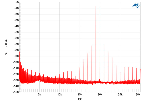
Fig.10 JMF HQS 7001, HF intermodulation spectrum, DC–30kHz, 19+20kHz at 50W peak into 8 ohms (linear frequency scale).
With the reduction in corrective feedback at high frequencies, high-order intermodulation products with an equal mix of 19 and 20kHz tones at 50W into 8 ohms were present, though they all lay at or below –72dB (fig.10). Commendably, the second-order difference product at 1kHz also lay below the level of the power supply–related spuriae.
The JMF HQS 7001's measured performance is typical of a high-power, solid state design with a class-AB output stage. Distortion will be lowest into 8 ohms, but the amplifier should not have had any problems driving JVS's Wilson Alexia V speakers to acceptably loud levels.—John Atkinson
Footnote 1: See fig.3 here.


