| Columns Retired Columns & Blogs |
Cut and Thrust: RIAA LP Equalization Page 2
In the summer 1978 issue of Stereo, technical editor Edward J. Foster wrote of the IEC revision: "What point is there in paying literally thousands of dollars for a stereo system capable of response to below 40Hz and then blowing it all on a sloppy subsonic filter?...The record-warp problem will not be solved by changes in equalization. It will be solved by changes in manufacturing technique and in improved quality control. Flat records can be made; it just takes a bit longer and costs a bit more." While in the "News and Views" section of High Fidelity, under the title "Phono Equalization: Fact, Fantasy, and Fallacy," this appeared, summarizing the feelings of many at the quality end of the audio industry: "[T]o us it seems foolish to enshrine inaccuracy of reproduction, however slight, to achieve a benefit that can be had via a route—a low-cut filter that turns over lower (perhaps at 15Hz) and rolls off more abruptly (12dB/octave) would be the logical choice—at once more effective and virtually without side effects." (footnote 4)
Footnote 4: This ignores the audible effects of LF phase distortion, which may be more significant than High Fidelity's author supposed.
Silly regulations bring the law into disrepute, and that's exactly what happened with the IEC amendment. Many manufacturers of hi-fi electronics agreed that the additional time constant was a bad idea, and elected not to implement it in their phono input stages. Not that the IEC ever conceded its error and backtracked: the additional 7950µs replay time constant has remained in its standard to this day.
Controversies about disc EQ have raged—or at least flared—at other times in the half-century since the RIAA standard came into being. Stanley Lipshitz put a cat among the pigeons in the June 1979 issue of the Journal of the Audio Engineering Society with an unprecedentedly detailed examination of the circuits used to apply RIAA/IEC deemphasis. He concluded that many of these were in error as a result of incorrect design equations being applied, or because the effects of other time constants in the circuit, and/or the influence of amplifier loop gain, were ignored. The corollary was another round in the nascent objectivist/subjectivist struggle in which it was claimed that many of the disparities heard between different amplifiers were due to nothing more exotic than significant departures from flat frequency response.
In the UK, an earlier spat followed the publication, in the May 1972 issue of Wireless World, of H.P. Walker's "Low-Noise Audio Amplifiers." The article demonstrated that shunt-feedback RIAA stages are more noisy than series-feedback equivalents (fig.5). There was no gainsaying Walker's analysis, but it rankled with Britain's greatest designer of DIY audio projects, John Linsley Hood, who favored the shunt-feedback circuit on the basis that it sounded superior. A protracted exchange in WW's letters pages ensued. Hood is probably best known for his minimalist, 10W, class-A amplifier (footnote 5), praised in recent years by none other than amplifier design's Mr. Minimalist, Nelson Pass (footnote 6). Hood may well have had a point, given the attention subsequently lavished on the common-mode-distortion performance of series-feedback circuits. But in later years he was inclined to ascribe the audible differences to disparities in high-frequency phase response caused by the inability of a series-feedback circuit to deliver a gain of less than 1 (a factor that Lipshitz identified in his JAES analysis). Maintaining his allegiance to the shunt-feedback circuit, JLH obviated its noise disadvantage in later designs by preceding it with a flat "head amp" stage (footnote 7).
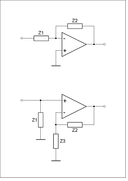
Fig.5 Shunt (top) and series feedback configurations. Gain of the shunt circuit is –Z2/Z1 and can be less than unity, but the input impedance, Z1, appears in series with the input voltage, worsening noise performance. Gain of the series circuit is (Z2+Z3)/Z3 and can never be less than 1 (when Z2=0), but Z1 now appears in parallel with the source, so noise performance is superior.
This concern over the high-frequency phase performance of disc-equalization circuits brings us nicely to a more recent development: compensation for the "Neumann ultrasonic time constant." (I have also seen this referred to as the "Neumann 4th pole," which is inaccurate terminology for reasons explained in the sidebar.) It originates, as far as I have been able to establish, in a book about tube amplifier design published in 1995 by Allen Wright, Australian founder of Vacuum State Electronics (footnote 8). In a section dealing with RIAA equalization, Wright pointed out that the inexorable rise of the RIAA preemphasis curve beyond 20kHz was not something that could be maintained in practice, otherwise it would threaten damage to the cutting head. So the manufacturers of disc-cutting amplifiers curtail the amplification at ultrasonic frequencies, typically by incorporating an additional time constant at around 50kHz. Wright wrote that this should be compensated for in the replay equalization, as shown in fig.6.
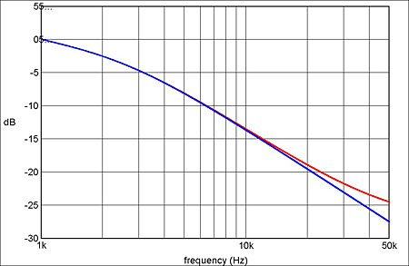
Fig.6 Change to the RIAA replay equalization (blue) that results from incorporating the 3.18µs "Neumann correction" (red).
This idea was later picked up by Jim Hagerman, who wrote about it in Audio Electronics (footnote 9). Since then, a number of preamp manufacturers, including AQVOX, darTZeel, and Whest Audio, have joined Vacuum State Electronics in amending their RIAA replay equalization to take account of this factor. Neumann's name became attached to the correction because its lathes—on which a great many of the world's vinyl records have been cut down the decades—have been reported to incorporate an additional record EQ time constant of 3.18µs (50.05kHz). As we will see, this isn't correct—but for the moment, let's assume that it is.
Fig.7 shows that implementing this correction makes little difference to frequency response within the audible range, the disparity being only 0.17dB at 10kHz, and just 0.64dB at 20kHz. So justification for this correction has sometimes rested more on the effects of in-band phase distortion. Let's look more closely at this, because claims about phase are all too often naive and misleading.
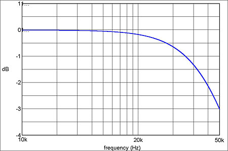
Fig.7 Difference between the red and blue traces in fig.6. The amplitude change at 20kHz is 0.64dB.
The key point to appreciate is that phase difference (input to output) and phase distortion (ie, a change in the shape of a complex waveform such as music) are not synonymous. If we plot the phase difference that results from adding a 3.18µs pole to the RIAA record characteristic, it appears—on the usual logarithmic frequency scale—as shown in fig.8. It is easy to point to phase differences of 5.7° at 5kHz and 21.8° at 20kHz and suggest that high fidelity has gone out of the window, but that is careless—very careless indeed.
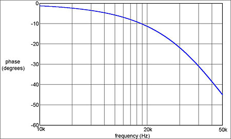
Fig.8 Phase shift associated with the amplitude response in fig.6, on the usual logarithmic frequency scale.
If, instead, we plot the phase difference on a linear frequency scale (fig.9), we begin to see a more pertinent picture. The straight line plotted on this graph represents the initial slope of the phase curve, which is –1.14° per 1000Hz. As this is equivalent to a constant, frequency-independent time delay of 3.18µs (the same as the filter time constant), it can be discounted: it introduces no phase distortion whatsoever. What will introduce phase distortion is the phase disparity between this line and the phase curve, which is plotted in fig.10. From this we see that the phase error at 5kHz is actually only 0.015° (equivalent to a time error of less than 0.01µs), and at 20kHz only 1.1° (equivalent to a time error of 0.15µs).
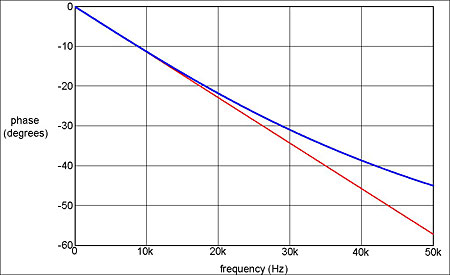
Fig.9 The phase curve in fig.8 transferred to a linear frequency scale, with a straight line added (red) to show the initial slope.
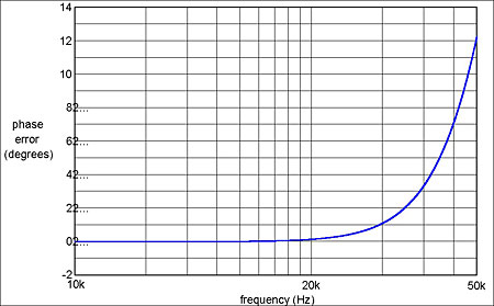
Fig.10 Difference between the blue and red traces in fig.9. It is only this difference that gives rise to phase distortion.
An alternative way of looking at this is to plot what is known as the group delay—the negative slope of the phase vs frequency curve (fig.11). The initial group delay of 3.18µs corresponds to that identified in fig.10. If we subtract this, then the largest in-band group-delay error is –0.44µs at 20kHz. Although most research into the audibility of phase distortion has been conducted at lower frequencies, tests of the audibility of minimum-phase anti-alias filters indicate that such a small amount of group-delay error at 20kHz is well below audibility (footnote 10) Readers who store 96kHz audio files on computer hard drives—examples are downloadable from www.2l.no/hires/index.html—can judge this for themselves by downloading from my website a freeware Windows utility I've written to simulate this phase distortion (footnote 11).
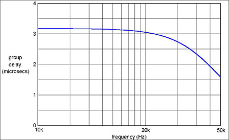
Fig.11 Group delay vs frequency for the amplitude response in fig.7. This is another way of depicting the phase distortion the amplitude error introduces.
Footnote 4: This ignores the audible effects of LF phase distortion, which may be more significant than High Fidelity's author supposed.
Footnote 5: See www.tcaas.btinternet.co.uk.
Footnote 6: Nelson Pass, "The PLH Amplifier," audioXpress, December 2005.
Footnote 7: "An RIAA Phono Cartridge Equalizer," Gramophone, November 1990.
Footnote 8: The Tube Preamp Cookbook, Vacuum State Electronics, 1995.
Footnote 9: "On Reference RIAA Networks," Audio Electronics, March 1999.
Footnote 10: D. Preis and P.J. Boom, "Perception of Phase Distortion in Anti-Alias Filters," Journal of the Audio Engineering Society, Vol.32 No.11, November 1984.
Footnote 11: RIAAPhaseErrors.zip from www.audiosignal.co.uk/freeware.
NEXT: Page 3 »
|
| |||||||||
- Log in or register to post comments


| Loudspeakers Amplification Digital Sources | Analog Sources Accessories Featured | Music Columns Retired Columns | Show Reports | Features Latest News Community | Resources Subscriptions |
 © 2024 Stereophile
AVTech Media Americas Inc., USA
All rights reserved

