Sidebar 3: Measurements All measurements were made after the YBA 2 had been preconditioned by running it at one-third full power into 8 ohms for an hour, which thermally stresses the amplifier to the maximum. Its heatsinks were very hot at the end of this period. Interestingly, however, those who say that solid-state components need no warmup should note that the amplifier's THD+noise, initially 0.09% for 1W into 8 ohms, dropped by a factor of more than five—to 0.016%—by the end of this preconditioning period. The YBA 2 HC's voltage gain measured 27.6dB into an 8 ohm load; its input impedance was pretty much to spec at 28.5k ohms. Despite the circuit's low amount of overall negative feedback, the YBA's output impedance, without the optional series output inductor, was low at 0.06 ohms across the audio band. Its noise level was very low, the S/N ratio measuring 83.2dB (left channel) and 92.8dB (right), both figures unweighted with a 22Hz-22kHz bandwidth and ref. 1W into 8 ohms. DC offset was negligible in both channels. The YBA 2's small-signal frequency response (fig.1) was well matched between channels and flat in the audio band, rolling off above 10kHz to reach -1dB just above 50kHz. The low frequencies were flat down to the generator's 10Hz limit. A 1kHz squarewave was correspondingly reproduced with flat tops, while a 10kHz squarewave (fig.2) revealed no overshoot or ringing, just a slightly lengthened risetime because of the ultrasonic bandwidth limiting. The optional series output inductor didn't affect the squarewave's risetime significantly. Channel separation was very high, though somewhat asymmetric between channels (fig.3). The amplifier was non-inverting.
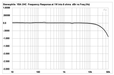 Fig.1 YBA 2 HC, frequency response at 1W into 8 ohms (right channel dashed, 0.5dB/vertical div.).
 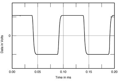 Fig.2 YBA 2 HC, 10kHz squarewave at 1W into 8 ohms.
 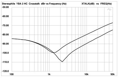 Fig.3 YBA 2 HC, crosstalk (from top to bottom at 50kHz): R-L, L-R (10dB/vertical div.). The manner in which the YBA 2 HC's distortion changed with frequency (fig.4) indicates the basic circuit must have good linearity, as, even with the modest amount of feedback employed, the overall level of THD+noise into 8 ohms hovers between 0.02% and 0.03% below 2kHz. Note, however, the rise in THD in the mid-treble and above. I suspect that this illustrates the circuit's limited open-loop gain-bandwidth product. When the loop is closed with negative feedback, that feedback can work its distortion-reducing trick only as long as there's a significant difference between the closed- and open-loop gains. With falling open-loop gain at ultrasonic frequencies, less distortion reduction occurs. Note also the approximate doubling of the distortion level as the load impedance is reduced from 8 to 4 ohms, and the even greater increase into 2 ohms (though this is still sufficiently low, provided the harmonic products are sonically benign second- and third-harmonic rather than the much more audible seventh-, ninth-, etc.).
 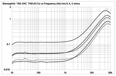 Fig.4 YBA 2 HC, THD+noise vs frequency at (from top to bottom): 4W into 2 ohms, 2W into 4 ohms, and 1W into 8 ohms (right channel dashed). Fig.5 shows both a low-level signal waveform (2W into 4 ohms) and the waveform of the distortion and noise residue once the fundamental 1kHz signal has been notched out by the analyzer. The distortion is clearly mainly second harmonic, though dropping the load to 2 ohms does somewhat raise the level of higher harmonics. This phenomenon can also be seen in figs.6 and 7, which show the output spectrum with the YBA reproducing a 50Hz tone at 1W into 8 ohms and 100W into 4 ohms, respectively. At low levels and higher impedances, the only harmonic worth mentioning is the second at 100Hz, which lies nearly 80dB down from the fundamental. At much higher levels into lower impedances, the second harmonic rises in level to -54.5dB (0.2%) and is joined by the third harmonic at nearly the same level (-56.7dB). The fourth through seventh harmonics can also now be clearly resolved above the FFT plots' floor of "grass," as can a splattering of higher harmonics, though these are all still very much below the levels of the dominant second and third harmonics. Note, however, that the 60Hz power-line frequency appears in fig.7, as do the 120Hz and 180Hz harmonics. Though these are all low in level, they do indicate that the 2 HC's power supply is a little undersized in absolute terms. I suppose this is why YBA makes the physically larger but nominally not much more powerful YBA 1.
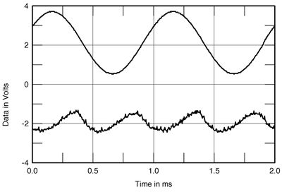 Fig.5 YBA 2 HC, 1kHz waveform at 2W into 4 ohms (top); distortion and noise waveform with fundamental notched out (bottom).
 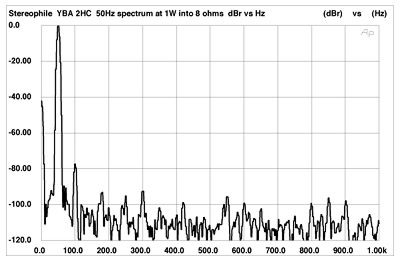 Fig.6 YBA 2 HC, spectrum of 50Hz sinewave, DC-1kHz, at 1W into 8 ohms (linear frequency scale). Note that the second harmonic at 100Hz is the highest in level, 78dB below the level of the 50Hz fundamental (0.01%).
 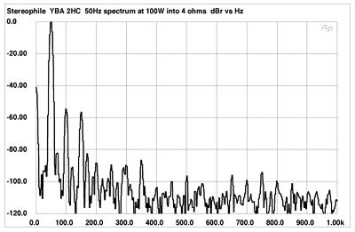 Fig.7 YBA 2 HC, spectrum of 50Hz sinewave, DC-1kHz, at 100W into 4 ohms (linear frequency scale). Note that the second and third harmonics, at 100Hz and 150Hz, are the highest in level.
Fig.1 YBA 2 HC, frequency response at 1W into 8 ohms (right channel dashed, 0.5dB/vertical div.). Fig.2 YBA 2 HC, 10kHz squarewave at 1W into 8 ohms. Fig.3 YBA 2 HC, crosstalk (from top to bottom at 50kHz): R-L, L-R (10dB/vertical div.). The manner in which the YBA 2 HC's distortion changed with frequency (fig.4) indicates the basic circuit must have good linearity, as, even with the modest amount of feedback employed, the overall level of THD+noise into 8 ohms hovers between 0.02% and 0.03% below 2kHz. Note, however, the rise in THD in the mid-treble and above. I suspect that this illustrates the circuit's limited open-loop gain-bandwidth product. When the loop is closed with negative feedback, that feedback can work its distortion-reducing trick only as long as there's a significant difference between the closed- and open-loop gains. With falling open-loop gain at ultrasonic frequencies, less distortion reduction occurs. Note also the approximate doubling of the distortion level as the load impedance is reduced from 8 to 4 ohms, and the even greater increase into 2 ohms (though this is still sufficiently low, provided the harmonic products are sonically benign second- and third-harmonic rather than the much more audible seventh-, ninth-, etc.). Fig.4 YBA 2 HC, THD+noise vs frequency at (from top to bottom): 4W into 2 ohms, 2W into 4 ohms, and 1W into 8 ohms (right channel dashed). Fig.5 shows both a low-level signal waveform (2W into 4 ohms) and the waveform of the distortion and noise residue once the fundamental 1kHz signal has been notched out by the analyzer. The distortion is clearly mainly second harmonic, though dropping the load to 2 ohms does somewhat raise the level of higher harmonics. This phenomenon can also be seen in figs.6 and 7, which show the output spectrum with the YBA reproducing a 50Hz tone at 1W into 8 ohms and 100W into 4 ohms, respectively. At low levels and higher impedances, the only harmonic worth mentioning is the second at 100Hz, which lies nearly 80dB down from the fundamental. At much higher levels into lower impedances, the second harmonic rises in level to -54.5dB (0.2%) and is joined by the third harmonic at nearly the same level (-56.7dB). The fourth through seventh harmonics can also now be clearly resolved above the FFT plots' floor of "grass," as can a splattering of higher harmonics, though these are all still very much below the levels of the dominant second and third harmonics. Note, however, that the 60Hz power-line frequency appears in fig.7, as do the 120Hz and 180Hz harmonics. Though these are all low in level, they do indicate that the 2 HC's power supply is a little undersized in absolute terms. I suppose this is why YBA makes the physically larger but nominally not much more powerful YBA 1. Fig.5 YBA 2 HC, 1kHz waveform at 2W into 4 ohms (top); distortion and noise waveform with fundamental notched out (bottom). Fig.6 YBA 2 HC, spectrum of 50Hz sinewave, DC-1kHz, at 1W into 8 ohms (linear frequency scale). Note that the second harmonic at 100Hz is the highest in level, 78dB below the level of the 50Hz fundamental (0.01%). Fig.7 YBA 2 HC, spectrum of 50Hz sinewave, DC-1kHz, at 100W into 4 ohms (linear frequency scale). Note that the second and third harmonics, at 100Hz and 150Hz, are the highest in level.


