For logistic reasons, VTL provided us with a separate pair of MB-1250s from the ones reviewed by JS. The measurements below thus reflect the pair delivered to Santa Fe.
My initial intent, after eyeballing the 24 separate tube bias settings in each of these huge VTL monoblocks (VTL recommends checking the bias monthly!), was to not check the bias before the tests. After all, our test amplifiers had come directly from the factory. Presumably the bias had been set correctly—something a buyer has a reasonable right to expect. But to be certain, I ran a few preliminary measurements, to judge their reasonableness. Upon finding that the power output was a little below spec, I elected to check the bias. According to the manual, the DC voltage across each bias resistor should have been 275–300mV. My readings were all under 130mV.
Hmmm. This was so far out of whack but consistent on all the tubes, that I checked with Luke Manley of VTL before making the huge increase needed to raise the bias to the level recommended in my manual. It's a good thing I did. With the test amplifiers set up at the factory for an optimum 5 ohm load, the correct bias setting was supposed to be 150mV. Both my owner's manual and the amp as received were wrong. Buyers should treat this as a caution. If the value in your manual differs markedly from the bias setting of the delivered amplifier, check with the factory before cranking the bias up. You could damage the amp or severely impact tube life at double the required bias, as I might have done had I followed the recommendation in my owner's manual. Severely shortening the life of 48 tubes (for the stereo pair) could be a very expensive mistake.
Because of the very high power output of the VTL MB-1250 and the thermal limitations of our test bench load, I did not run a standard 60-minute preconditioning test. This test, however, is not truly relevant to tube amplifiers anyway—it's intended to thermally stress solid-state amplifiers with class-B output stages. I did allow the VTL to warm up for approximately 30 minutes before proceeding—about the amount of time it took me to rebias the tubes in the single monoblock I measured.
The amplifier ran quite warm in operation—but no warmer than you would expect from the forest of tubes. Its input impedance measured from 170k ohms to 270k ohms depending on operating condition (triode or tetrode, balanced or unbalanced). An input impedance this high is very difficult to measure accurately: the readings show very small variation with changes in the Audio Precision System Ones' source impedance, and as with most tube amplifiers, they also fluctuate slightly. But the tests confirm a very high input impedance, which is generally desirable. Suffice it to say that I know of no preamplifier which will experience an impedance mismatch when connected to the MB-1250.
The amplifier's voltage gain into 8 ohms in balanced mode was 28.2dB (triode), and 30.3dB (tetrode). It was virtually the same for unbalanced inputs. The VTL is non-inverting, a positive-going input resulting in a positive-going output, and in the balanced mode pin 2 is positive. DC offset at the output measured 1.2mV. The S/N ratio for various operating conditions is shown in Table 1, rounded off to the nearest dB.
Table 1: VTL MB-1250 S/N Ratio
(ref. 1W/8 ohms)
| Measurement Bandwidth | Triode balanced/unbalanced | Tetrode balanced/unbalanced |
| 22Hz–22kHz | 85dB/56dB | 80dB/54dB |
| 10Hz–500kHz | 79dB/56dB | 77dB/54dB |
| A-weighted | 92dB/69dB | 90dB/66dB |
The noise levels in the balanced mode were good, but relatively poor when the amplifier was driven unbalanced. The balanced readings were taken with the balanced input shorted out, the unbalanced with both the unbalanced and balanced inputs shorted out (not shorting the balanced input made little difference in the balanced mode measurement).
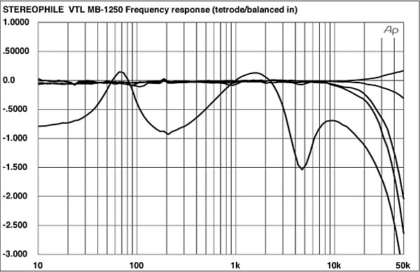
The output impedance of the MB-1250 in the triode mode measured around 0.92 ohms at 20Hz and 1kHz, increasing to a maximum of 1 ohm at 20kHz. The corresponding figures for the tetrode mode were 1.17 ohms and 1.26 ohms. While far lower than we have measured with some tube amplifiers, these are still relatively high values on an absolute basis and will affect the frequency response into most real-world loads (see below).
For both the triode and tetrode operation, most of the measurements were taken in balanced operation, though unbalanced measurements for frequency response and THD+noise frequency are also presented.
Triode operation
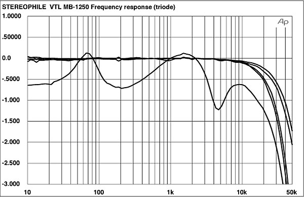
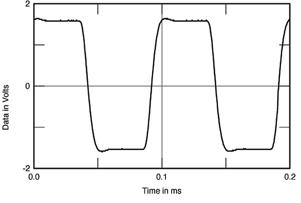
Fig.1 shows the frequency response of the MB-1250. The HF rolloff is just slightly faster in the balanced mode, and the effect of the fairly high output impedance on the response is evident. While it is within ±1dB up to 20kHz, it should be audible (and will vary slightly with different loudspeakers). The output waveform of a 10kHz squarewave is shown in fig.2. There is a slight overshoot at the leading edge but no ringing. The overshoot is also just visible in the 1kHz squarewave (not shown).
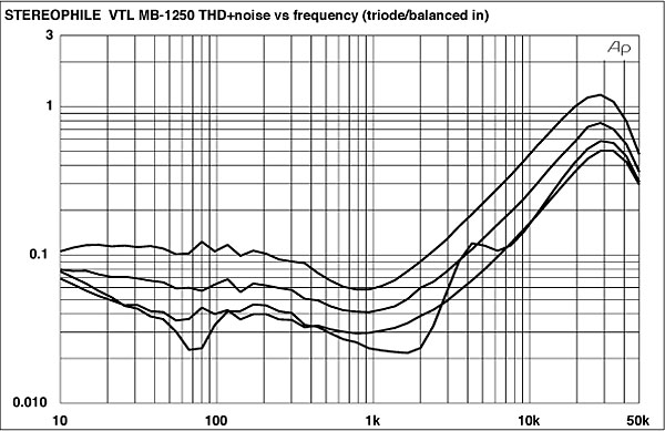
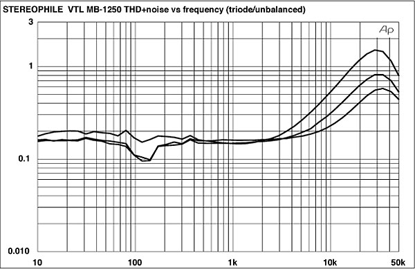
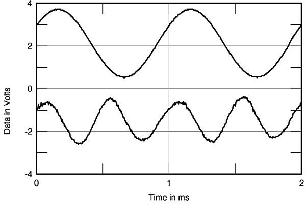
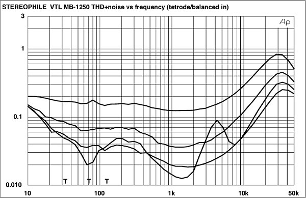
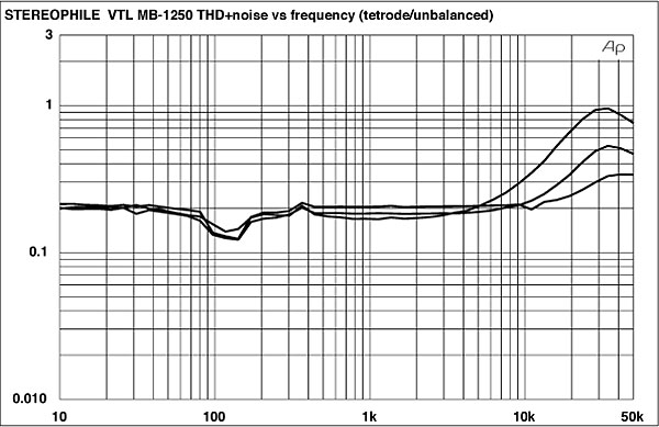
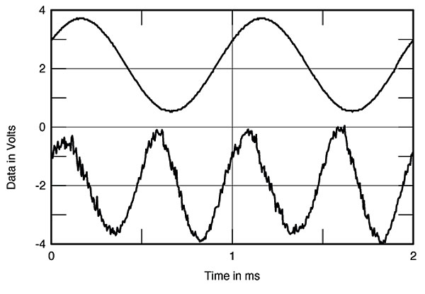
The THD+Noise curves in figs.3 and 4 show a rising level of distortion at higher frequencies but an overall reasonable performance, particularly up to 10kHz. The distortion for unbalanced inputs (fig.4) is affected by the higher noise levels in this mode. The THD+noise waveform at 2W into 4 ohms in triode mode is shown in fig.5. It is heavily second-harmonic plus noise.
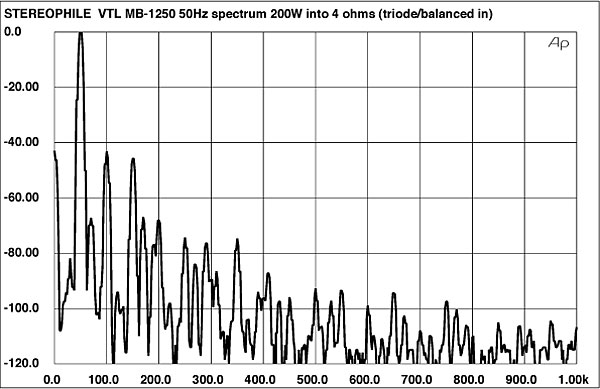
Because of the high power output capabilities of the MB-1250, I restricted the power in the following output spectrum tests to 200W, rather than the 2/3 power usually used. (These tests take longer than the clipping measurements and I did not want to risk our test load; for the same reason the 50Hz spectrum into our simulated real load was not run here.)
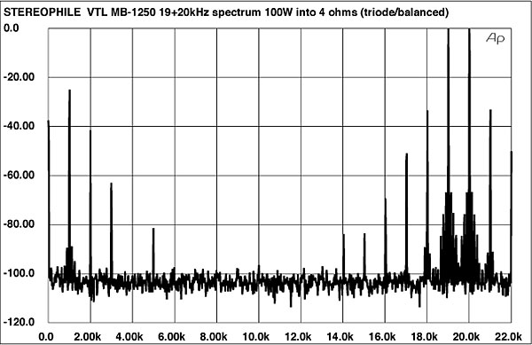
The output spectrum resulting from a 50Hz input at 200W into 4 ohms is shown in fig.6. The artifacts are relatively high in level (–43dB or about 0.7% at 100Hz and –46dB or about 0.5% at 150Hz). Fig.7 is a similar spectral plot showing the intermodulation products present in the output resulting from a 19+20kHz input signal at 100W into 4 ohms (the highest output possible with this signal prior to visible clipping). The 1kHz IM product is very high in level: just –25dB or 6%. At 18kHz and 21kHz, the IM lies at about –33dB or 2%. (Keep in mind, however, that 100W is a very high power output at these frequencies—far above the power handling capability of a real-world tweeter). The spectral response at 59W into 8 ohms was very similar (not shown), though the artifact levels were slightly lower (approximately 4% at 1kHz and 1.8% at 18kHz and 21kHz, respectively).
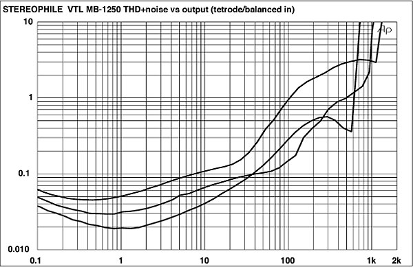
The manner in which the THD+noise level changes with output power (at 1kHz) for the MB-1250 in triode mode is shown in fig.8. The gradual rise in distortion without a well-defined breakpoint or "knee" is typical of tube amplifiers. Here the distortion rises gradually above about 1W. The output is nearly the same into either 2 or 4 ohms, less into 8 ohms. The discrete clipping levels are given in Table 2. Note that these are given for 3% THD+noise at 1kHz, instead of our standard 1%. Even here, the MB-1250 falls about 90W short of its rated power output.
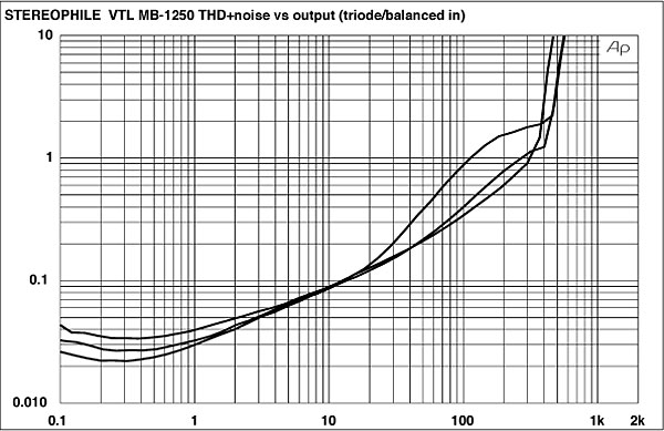
Table 2: VTL MB-1250
Discrete Clipping Power
(3% THD+noise at 1kHz)
| Impedance ohms | Triode W (dBW) | Tetrode W (dBW) |
| 8 | 408.5 (26.1) | 644 (28.1) |
| Line | 115V | 115V |
| 4 | 510.1 (24.1) | 952 (26.8) |
| Line | 116V | 115V |
| 2 | 508 (21.1) | 1111 (24.5) |
| Line | 115V | 113V |
Tetrode operation
The frequency response in tetrode mode is shown in fig.9. It is similar to the triode result with two exceptions: the unbalanced result is slightly flatter above 10kHz and the deviations into the simulated real load are slightly greater (reflecting the marginally higher tetrode output impedance). The tetrode squarewave response was virtually identical to the triode except for a just slightly less well damped overshoot (the difference is barely visible on our plots—not shown here—though slightly easier to see directly off an oscilloscope).
The distortion curves in figs.10 and 11 show the same pattern as the triode results, with small but not dramatic differences in magnitude. The distortion waveform remains second-harmonic with some higher-order components plus noise apparent (fig.12).
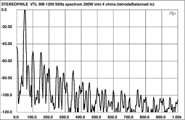
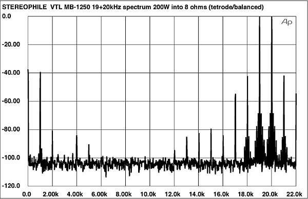
As with the triode mode, I restricted the power in the spectral response tests to 200W. A plot showing the output spectrum resulting from the amplifier driving 50Hz at 200W into 4 ohms is shown in fig.13 Though still relatively high in level (–49dB or 0.35% at 100Hz and –50dB or 0.3% at 150Hz), the artifacts here are somewhat lower than in the triode mode. The 1kHz IM distortion product resulting from a 19+20kHz input signal at 200W into 8 ohms (fig.14) remains high, though, at –39dB or about 1%, lower than in the triode mode (the result here is at a higher output). The 18kHz and 21kHz IM products are at about –42dB or 0.7%.
The tetrode variation of THD+noise with output power is shown in fig.15. The general trend is the same as in the triode mode, though the output levels are higher. Again, as in the triode mode, the output falls short of the specified levels. The 3% THD+noise levels at 1kHz (clipping) are shown in Table 2.
The measurements of the VTL MB-1250 are respectable (with the exception of the rather high S/N in the unbalanced mode), though not remarkable in any way save the very high power output (for a tube amplifier).—Thomas J. Norton


