Editor's Note: One-bit DAC chips in the 21st century, where the analog output signal is reconstructed from a very high-rate stream of pulses, are ubiquitous. But a quarter-century ago, those chips were only just beginning to stream from the chip foundries. In this feature, we aggregate Stereophile's 1989 coverage of the then-new technology, starting with Peter van Willenswaard on the basics.—John Atkinson.
Peter van Willenswaard Opens
1989 may well become the year of the D/A converter (DAC). CD-player manufacturers have, almost without exception, launched research projects focusing on this problem area of digital audio; many of these projects are already a year old. This is, however, by no means the only imperfection keeping us away from the high-quality sound we have come to suspect is possible with digital audio media, and maybe not even the most important. There are other factors: jitter, for instance, not an amplitude- but a time-related defect in the digital data stream or in the clock signals controlling the proper functioning of the decoder, digital filter, and converter circuits. It can be shown that jitter will demodulate as a function of the momentary steepness of the converted audio signal, which will cause very low-level but very awkward distortions. Then there is the choice of the digital low-pass filter. To think you're out of the minefield once you have decided to stay away from the various types of high-order analog filters and instead include a digital filter in the design of a CD player, is a misconception: there are about as many different digital filter configurations as there are analog ones! Moreover, I would not at all be surprised if two identical digital filter configurations of different manufacture sounded different. Until now, relatively little work has been done to investigate the relationship between configuration and sound.
Besides these and other known points, there are almost certainly a couple of problem areas we haven't come across yet. One can be equally sure that this new technology still hides from us an interesting collection of as yet unthought-of possibilities.
Zero-crossing distortion
In view of what I'll be saying in the rest of this article, it is essential that the reader have a precise understanding of the zero-crossing problem of the standard DAC, so I will discuss it first extensively. If you know already, you can skip this paragraph. The easiest way is to start at the beginning. What would be an ideal way to convert an analog signal into a digital one? The first step would be to cut the waveform into 44,100 samples per second (footnote 1). Then we would like to know if the amplitude in a given sample of the signal were positive or negative; that information would be stored in the first bit, a 1 for positive or a 0 for negative; we'll call it our sign-bit. Next we would see if the absolute value of the investigated amplitude (disregarding whether it is positive or negative) is larger or smaller than our largest magnitude-bit; if so, this bit will be set to 1; if not, it will remain 0. Our digital word is now two bits long, and in the case of a large positive value it will read 11. Next we will try the sum of the largest magnitude-bit and the second-largest magnitude-bit; if our sample is larger still, the second bit will be set to 1 too; if not, it will be 0. Let us suppose our sample is larger than the largest magnitude-bit but not as large as the first two together, and thus add a 0 to our digital word, which becomes 110. Now if we continue to try to determine whether the next (smaller) bit should be on or off, and the next (even smaller), and so on, we will zoom in with more and more precision on the exact value of the sample. And, while doing so, our digital word will grow until we have determined the 15th magnitude-bit: one sign-bit plus 15 magnitude-bits makes 16 bits (the limit given by the generally adopted digital audio standard).
For low-level signals this sign+absolute-magnitude–system has a friendly character. The first bit only indicates + or –, the next 10 bits or so remain stable at 0, and only the smallest bits will change value from one sample to the next. There is no great difference of ratio between these small bits, so temperature drift is no problem and there won't be any nasty glitches (narrow but pretty high pulses between the samples, of digital origin) where we least want them: in the softest part of a musical signal (footnote 2).
So why aren't real-world A/D and D/A converters built like this? For two reasons. One is that digital circuitry cannot easily perform arithmetic operations with sign-and-magnitude–coded signals. The other is that A/D and D/A converters, developed for measurement purposes, already exist. Now in many measurement applications the value to be measured is either a positive or a negative one, rarely one alternating around 0V. So A/D and D/A converters were designed to operate single-sided, the digital codes starting 000...000 for the zero value and counting their way up to the maximum 111...111 to describe their largest sample value (footnote 3). In audio we having nothing but alternating signals, so if we want to use the existing digital technology, we shall have to define an artificial zero line somewhere in the operational window offered by the A/D or D/A converter of our choice. The most logical place to put that artificial zero is in the middle of that window, halfway between 000...000 and 111...111, the converter's minimum and maximum values. Which is what Sony and Philips did. Halfway is where the largest bit (Most Significant Bit, or MSB) must come into action if the DAC's output voltage is to grow any further. For audio either 011...111 or 100...000 had to be defined as "digital zero."
In fact, the coding used still uses the MSB to indicate the sign of the signal, 1 for negative and 0 for positive, thus 100...000 is the lowest value and 011...111 the highest. The two choices for digital zero therefore become 111...111 and 000...000.
Now let's take a look at what will happen around digital zero, which we will assume to be 000...000. One step up the digital staircase poses no problem: 000...001: the Least Significant Bit (LSB) is switched on. One such tiny step down, however, changes the world: 111...111. All bits change value at the same time. This causes glitches (because the bits usually don't switch in exact synchronization) and possibly other kinds of "digital noise." The second observation to be made is: the difference between the voltage 000...000 generated at the converter output, and the voltage corresponding to 111...111, must be exactly one smallest bit (1 LSB), one step down the staircase. It usually isn't. If the error here is greater than 0.5 LSB, the converter is no longer monotonic. That is, at this point the staircase doesn't look like a staircase any more. This causes severe distortions at low signal levels (and dither doesn't help!). In practice, errors of 1 LSB are found to be quite common, and errors of several LSBs are not exceptional (footnote 4).
Why is it so difficult to make D/A converters perfectly monotonic? I'll repeat what I said a little earlier: the difference between the voltage 000...000 generated at the converter output and the voltage corresponding to 111...111 must be exactly one smallest bit, 1 LSB. The MSB must therefore be exactly one bit greater than the sum of all the other bits together (011...111). The ratio between the MSB and the LSB is 215, in decimal language 32,678. If we tolerate 0.5 LSB error, the precision of the MSB must be within 0.5/32,768 = 0.000015, or 0.0015% regardless of temperature and power-supply voltage changes. And that is a serious problem! Ever try to cut a bar to a 1-meter length within 0.015mm? Such a tolerance is hard to realize in serial manufacturing. That's why you'll find a trim pot next to the D/A converter in so many CD players. But that doesn't ban temperature drift: trim it to be optimal today, and tomorrow it may be off by 1 LSB or more.
Developments
It is remarkable that it took so long for the zero-crossing distortion (also called MSB error) to be widely recognized as a real problem.
On the other hand, it was one of the reasons Philips had wanted no more than 14-bit encoding. Sony demanded 16 bits for the CD standard (thank goodness), so Philips had to do something about the remaining two-bit gap, and invented 4x-oversampling (thank goodness again). Then the matter seemed to go into hibernation, perhaps because it took reviewers years to figure out what exactly was going on inside CD players (footnote 5). And it surely helped when the CBS CD-1 test disc became available in 1987.
Now I want to take a look at what's happening at the D/A-conversion front lines. In measurement technology, developments are incredibly fast; they seem to invent a new or faster way of D/A conversion every week. That in itself is quite promising for the future of digital audio. But in present digital audio we can distinguish three trends. There are some overlaps in the newly chosen technologies between the various manufacturers, so be careful not to pin them down as soon as one of their names appears in one category.
More bits? This trend is found with the majority of the Japanese manufacturers. Not really surprising, as they have always aimed at increasingly better-looking specifications. Early in 1988 we got a number of 18-bitters, and in the fall Denon and Accuphase introduced 20-bitters. This suggests that the MSB problem in the 16-bitters is under control, but that is not at all the case (footnote 6). It only means that the LSI industry has succeeded in putting more bits onto a converter chip. If you look at the data sheets of these converters, you'll find that most of them specify monotonicity only up to 15 or 16 bits. Not bad for 16-bit audio, but in flagrant conflict with the 18-bit banner. Let us repeat the above calculation of the required tolerances for the MSB value. The LSB in an 18-bit system is four times smaller than with 16 bits. Hence 0.0015/4% = 0.0004%. Take a bar and try to cut a length of 1 meter with 0.004mm or 4µm precision. Suppose you succeed; the moment you touch it, it will be out of spec because of the warmth of your hand. So to make a true 18-bit converter (monotonic from the start and remaining so over a reasonable temperature range) is very, very difficult.
A true 20-bit converter is almost a physical impossibility. Accuphase didn't have to worry about price but it is no wonder Denon decided to use an 18-bit converter and add a few discrete transistors to have an input for bits 19 and 20, and feed the output signals to a summing amp. The LSB here is again four times smaller than in the 18-bit case, so an MSB tolerance of 0.0001% follows. When physicians define super-small deviations, they speak in parts-per-million (ppm). The calculated 0.0001% is one ppm. Reference currents inside D/A converters are in one way or another set by one (or more) resistor(s). A very low-temperature coefficient resistor can be found in a good-quality metal-film resistor. The temp.coeff. of such a resistor is 1 ppm/°C. Are these converters in a constant-temperature oven? (And we haven't even spoken of semiconductor drift yet!)
Perfectionists who unknowingly demand a minimum of, say, 24 bits for good audio should take notice. I know who I am talking to; I used to be one of them.
Now, are these higher numbers than 16 bits therefore useless? No, not quite. The rounding-off process in the digital filter can be performed at a lower level, and that can be an advantage. And smaller vertical steps in the output staircase (footnote 7) are a welcome move closer to a stepless analog signal. But more bits do not (given the technological boundaries of our day) present a solution to zero-crossing distortion.
16 bits improved: Philips/Marantz
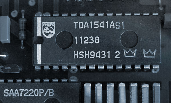
There are, however, a few solutions for arriving at a better zero-crossing behavior without opting for a totally new conversion technology. Good old Philips found one. They were forced to, mind you, because their original SAA7220/TDA1541 filter/converter combination showed large zero-crossing errors, and a lot of difference between channels. But they didn't go for the Burr-Brown solution of adding an adjustment pin to the converter chip, prescribing the use of an external trim pot, and praying for constant temperature. When they announced their new SAA7220P/B digital filter and TDA1541A converter, I didn't immediately understand what exactly had changed. Until I did a test of the new (and beautiful-sounding!) Marantz CD12/CDA12 CD-drive/DA-converter set, which is marketed in the US as the Philips LHH1000. In the accompanying literature a digital DC offset was mentioned as a cure for zero-crossing distortion. The zero-level had been shifted, it said, to a –63dB level. Some research made it clear that the SAA7220P/B is doing just that. The CDA12/LHH1000 happens to be an early user of this new digital filter, but others are to follow. So how does 7220/B do it? It adds a small binary number to all the digital words before they leave the filter. In this small binary number, all bits are zero but for the 11th: 0000000000100000. Thus, the code that was "digital zero" (the MSB turnover point) is shifted to a level slightly higher than the D/A converter's zero-crossing point. The distortion caused by the MSB error of the converter now happens at a –63dB signal level where it will be masked by the relatively strong signal. The signal-zero transition is now from 1000000000011111 to 1000000000100000, so only the last six bits change value here, which is far less harmful than all bits changing at once (including the most difficult, the MSB) (footnote 8). Philips also narrowed production tolerances on the 1541A converter and selects them: there is a better 1541A S version, an S1 version, and an S1 Crown version, the top selection. The CDA12 is using one of those. Both SAA7220P/B and selected TDA1541A can be ordered from Philips; their combined cost is just under $100. If you consider upgrading and your older chips are not mounted on IC sockets, think again and don't. Print tracks are very thin and very likely to be irreparably damaged when trying to desolder the existing chips. I would also like to note here that it isn't just these new chips that place the Marantz CD12/CDA12 among the world's top three CD players (yes, it's that good, in my opinion). It contains a very sophisticated de-jitter circuit. Taking one look inside and trying to lift one (if you have a chance) will tell you the rest.
16 bits improved: Technics/Panasonic
Technics has come up with a clever one too. They call it 4-DAC, meaning two DACs per channel. Of course Technics is not the only one to use two converters in tandem, but they've done something special. They designed a new processing chip to be inserted between the digital filter and the converters. This chip has two outputs, each feeding one converter. Inside the chip the (digital) signal is split into the positive and negative signal halves. These halves are then each converted by their own DAC, and the DAC outputs are summed with an op-amp. This structure bears some resemblance to a class-B push-pull output stage, as each converter is only active during its own signal half. The fun of it is, that it is now no longer necessary to use the DACs for alternating signals, thus avoiding all the problems mentioned above. Instead, the converters can now be used as they were designed to be used: single-sided. The MSB error then occurs at around –6dB, and is totally masked by the music at this very high level. There are a few tradeoffs I can think of. If there exists a DC offset voltage between the inputs of the summing amp, this will be a new zero-crossing error. There are op-amps with a sufficiently low input offset voltage (and temperature drift), but these are quite expensive, say $30 each. I've asked Technics which one they use, but haven't received a clear answer yet. A second thing is that they use 18-bit converters and switch them up by 2 bits for signals below –12dB, which is how they realize their 20-bits claim. I tend to frown at such complexities. As for the 18-bit converter itself, see my earlier objections. Thirdly, between each converter and the summing amp sits a class-AA amplifier stage, again a very complex circuit, and right where you find enormously high rise-times. All together, this makes the outcome rather uncertain as far as sound quality is concerned. I have never heard such a CD player under circumstances well-known to me. The explained technology will be incorporated in CD players like SL-P333 and SL-P999 (coming soon). Fewer bits, higher speed: Philips/Technics I think it was in 1984, at the Eindhoven AES convention, that Robert Adams of dbx presented a paper on their 1-bit adaptive delta-modulation A/D- and D/A-conversion system. I can remember the Philips people standing around smiling in compassion. 1 bit? Ridiculous.
In 1988, Philips announced their own 1-bit conversion system, the bit-streamer. The first Philips chip containing a 256-fold oversampling digital filter and a 1-bit D/A converter already exists: the SAA7320. It's even available, in Japan, where it was spotted by a Dutch colleague last December. The SAA7320 is a first step and not yet fit for hi-fi applications; it is meant for the portables market. The idea is very promising, though. A 1-bit converter can't be other than linear, as there simply aren't enough bits to create a ratio problem: there is only one. Of course, you need a very high clock rate if you want to describe an audio signal with just 1 bit. Hence the 256x-oversampling, resulting in an 11.3MHz data stream at the output of the converter. A second advantage becomes immediately apparent: output filtering can be very simple; a first-order network will do. A second-generation chip is under way, the SAA7240, but I'm afraid I can't tell you much about it. You can't imagine how difficult it is to find the right person in Eindhoven to get the information you want. Maybe I'm too close to my inventive compatriots; the wood for the trees and all that.
According to my calculations, 256x-oversampling can cover only 8 bits in a proper manner. I wonder what happened to the remaining information of the 16-bit input signal. The theoretical noise floor in such a system is –58dB (not –48dB, because delta modulation happens to be inherently more silent). So something additional had to be done. Philips employs a second-order noise shaper to arrive at a –90dB noise floor, but I can't see how this recovers the rest of the information present at the input of the digital filter, and I wonder what it sounds like. Still, I cannot suppress the intuitive feeling that such a 1-bit system is the way to go.
Technics has been working on something similar. That is not as surprising as it may seem, for there has been cordial cooperation between Matsushita and Philips since the 1920s. The Technics people, however, halted at 32x-oversampling. They bought a third-order noise-shaper idea from Japan's National Telephone Company (NTT) to get the noise floor down. And they developed a quasi–4-bit PWM D/A converter to recover the audio signal. Such a PWM converter is a clever thing. Like a 1-bit converter, it has only one amplitude, which excludes an MSB error. The mean value of its output bit stream determines the momentary signal amplitude, the modulation being transferred through variations in pulse-width. Here, too, the output data stream is of very high frequency, and first-order filtering suffices. Again, as with Philips' 1-bit, my calculations indicate an information loss of 7 bits, but let us wait and judge the practical result. The entire process is called MASH, and will be implemented in the Technics/Panasonic SL-P777 CD player planned for launch in late 1989.
Postscript: In my report, I mentioned that Matsushita, in cooperation with NTT, the Japanese equivalent of Bell Labs, had developed a 32x-oversampling, quasi-4-bit PWM DAC, using a third-order noise shaper, which will appear in Technics CD players toward the end of 1989. Well, my news was already obsolete, as these so-called "MASH" converters were available in three CD players in Technics' European line at the end of March 1989: the SL-P333, SL-P555, and SL-P777. ("MASH" is an awkwardly derived acronym for their patented Multi-stAge noiSe-sHaping PWM topology.)
It must have been a last-minute decision for Matsushita to include this new technology in commercial players, as these models' front panels still say "18-" or "20-bit/8x-oversampling." The company also seems a little embarrassed about how to promote fewer bits to the European buying public while other companies are still proudly announcing more bits and higher rates of over-sampling.—Peter van Willenswaard
Footnote 1: Since we're starting all over again, I'm tempted to also adopt a higher sampling rate, but I won't; it's simply not the issue here.
Footnote 2: There is one small problem: we have two digital codes for 0V instead of one: a rather naive endeavor to define plus-zero and minus-zero; it makes this system a little less straightforward, but let's stick to the main issues.
Footnote 3: Again, reality is slightly different, but as it has no principal implications, I avoid this potentially confusing issue.
Footnote 4: The undithered tone at exactly –90.31dBFS that we use in Stereophile tests of digital audio products examines the imbalance between a single LSB amplitude and the amplitude when all the bits change value. See fig.8 here for an example of a good DAC chip and fig.7 here at for a relatively poor example.—John Atkinson
Footnote 5: Or they just weren't interested, because of the disappointing sound of the first generation of CD players. I made that mistake.
Footnote 6: To be honest, a number of 18-bit converters actually are slightly better than the last generation of 16-bitters. Slightly better on a 16-bit scale, that is.
Footnote 7: I must note here that I have never been able to display on an oscilloscope screen the smaller steps promised by an 18- or 20-bit conversion. One explanation would be that the test signals on the various test CDs I use are too simple and bluntly impose 16-bit steps. Another is that today's digital filters aren't yet smart enough in their calculations.
Footnote 8: The situation is slightly more complicated. A 0dB signal will (digitally) clip on one side because of the (digital) DC shift, if no further measures are taken. The SAA7220P/B therefore also downscales all signals by a small factor to enable a distortion-free 0dB. Consequently, a few codes at the other end of the DAC will no longer be useful.
1989 may well become the year of the D/A converter (DAC). CD-player manufacturers have, almost without exception, launched research projects focusing on this problem area of digital audio; many of these projects are already a year old. This is, however, by no means the only imperfection keeping us away from the high-quality sound we have come to suspect is possible with digital audio media, and maybe not even the most important. There are other factors: jitter, for instance, not an amplitude- but a time-related defect in the digital data stream or in the clock signals controlling the proper functioning of the decoder, digital filter, and converter circuits. It can be shown that jitter will demodulate as a function of the momentary steepness of the converted audio signal, which will cause very low-level but very awkward distortions. Then there is the choice of the digital low-pass filter. To think you're out of the minefield once you have decided to stay away from the various types of high-order analog filters and instead include a digital filter in the design of a CD player, is a misconception: there are about as many different digital filter configurations as there are analog ones! Moreover, I would not at all be surprised if two identical digital filter configurations of different manufacture sounded different. Until now, relatively little work has been done to investigate the relationship between configuration and sound.
In view of what I'll be saying in the rest of this article, it is essential that the reader have a precise understanding of the zero-crossing problem of the standard DAC, so I will discuss it first extensively. If you know already, you can skip this paragraph. The easiest way is to start at the beginning. What would be an ideal way to convert an analog signal into a digital one? The first step would be to cut the waveform into 44,100 samples per second (footnote 1). Then we would like to know if the amplitude in a given sample of the signal were positive or negative; that information would be stored in the first bit, a 1 for positive or a 0 for negative; we'll call it our sign-bit. Next we would see if the absolute value of the investigated amplitude (disregarding whether it is positive or negative) is larger or smaller than our largest magnitude-bit; if so, this bit will be set to 1; if not, it will remain 0. Our digital word is now two bits long, and in the case of a large positive value it will read 11. Next we will try the sum of the largest magnitude-bit and the second-largest magnitude-bit; if our sample is larger still, the second bit will be set to 1 too; if not, it will be 0. Let us suppose our sample is larger than the largest magnitude-bit but not as large as the first two together, and thus add a 0 to our digital word, which becomes 110. Now if we continue to try to determine whether the next (smaller) bit should be on or off, and the next (even smaller), and so on, we will zoom in with more and more precision on the exact value of the sample. And, while doing so, our digital word will grow until we have determined the 15th magnitude-bit: one sign-bit plus 15 magnitude-bits makes 16 bits (the limit given by the generally adopted digital audio standard).
It is remarkable that it took so long for the zero-crossing distortion (also called MSB error) to be widely recognized as a real problem.
There are, however, a few solutions for arriving at a better zero-crossing behavior without opting for a totally new conversion technology. Good old Philips found one. They were forced to, mind you, because their original SAA7220/TDA1541 filter/converter combination showed large zero-crossing errors, and a lot of difference between channels. But they didn't go for the Burr-Brown solution of adding an adjustment pin to the converter chip, prescribing the use of an external trim pot, and praying for constant temperature. When they announced their new SAA7220P/B digital filter and TDA1541A converter, I didn't immediately understand what exactly had changed. Until I did a test of the new (and beautiful-sounding!) Marantz CD12/CDA12 CD-drive/DA-converter set, which is marketed in the US as the Philips LHH1000. In the accompanying literature a digital DC offset was mentioned as a cure for zero-crossing distortion. The zero-level had been shifted, it said, to a –63dB level. Some research made it clear that the SAA7220P/B is doing just that. The CDA12/LHH1000 happens to be an early user of this new digital filter, but others are to follow. So how does 7220/B do it? It adds a small binary number to all the digital words before they leave the filter. In this small binary number, all bits are zero but for the 11th: 0000000000100000. Thus, the code that was "digital zero" (the MSB turnover point) is shifted to a level slightly higher than the D/A converter's zero-crossing point. The distortion caused by the MSB error of the converter now happens at a –63dB signal level where it will be masked by the relatively strong signal. The signal-zero transition is now from 1000000000011111 to 1000000000100000, so only the last six bits change value here, which is far less harmful than all bits changing at once (including the most difficult, the MSB) (footnote 8). Philips also narrowed production tolerances on the 1541A converter and selects them: there is a better 1541A S version, an S1 version, and an S1 Crown version, the top selection. The CDA12 is using one of those. Both SAA7220P/B and selected TDA1541A can be ordered from Philips; their combined cost is just under $100. If you consider upgrading and your older chips are not mounted on IC sockets, think again and don't. Print tracks are very thin and very likely to be irreparably damaged when trying to desolder the existing chips. I would also like to note here that it isn't just these new chips that place the Marantz CD12/CDA12 among the world's top three CD players (yes, it's that good, in my opinion). It contains a very sophisticated de-jitter circuit. Taking one look inside and trying to lift one (if you have a chance) will tell you the rest.
Technics has come up with a clever one too. They call it 4-DAC, meaning two DACs per channel. Of course Technics is not the only one to use two converters in tandem, but they've done something special. They designed a new processing chip to be inserted between the digital filter and the converters. This chip has two outputs, each feeding one converter. Inside the chip the (digital) signal is split into the positive and negative signal halves. These halves are then each converted by their own DAC, and the DAC outputs are summed with an op-amp. This structure bears some resemblance to a class-B push-pull output stage, as each converter is only active during its own signal half. The fun of it is, that it is now no longer necessary to use the DACs for alternating signals, thus avoiding all the problems mentioned above. Instead, the converters can now be used as they were designed to be used: single-sided. The MSB error then occurs at around –6dB, and is totally masked by the music at this very high level. There are a few tradeoffs I can think of. If there exists a DC offset voltage between the inputs of the summing amp, this will be a new zero-crossing error. There are op-amps with a sufficiently low input offset voltage (and temperature drift), but these are quite expensive, say $30 each. I've asked Technics which one they use, but haven't received a clear answer yet. A second thing is that they use 18-bit converters and switch them up by 2 bits for signals below –12dB, which is how they realize their 20-bits claim. I tend to frown at such complexities. As for the 18-bit converter itself, see my earlier objections. Thirdly, between each converter and the summing amp sits a class-AA amplifier stage, again a very complex circuit, and right where you find enormously high rise-times. All together, this makes the outcome rather uncertain as far as sound quality is concerned. I have never heard such a CD player under circumstances well-known to me. The explained technology will be incorporated in CD players like SL-P333 and SL-P999 (coming soon). Fewer bits, higher speed: Philips/Technics I think it was in 1984, at the Eindhoven AES convention, that Robert Adams of dbx presented a paper on their 1-bit adaptive delta-modulation A/D- and D/A-conversion system. I can remember the Philips people standing around smiling in compassion. 1 bit? Ridiculous.
Footnote 1: Since we're starting all over again, I'm tempted to also adopt a higher sampling rate, but I won't; it's simply not the issue here.


