On the face of it, the MG-20 is not very sensitive, 2.83V raising an estimated 80.5dB at 1m (B-weighted). In practice, however, the speaker's line-source radiation pattern will partially compensate for this. (The level of a true line-source speaker doesn't fall off as quickly with distance as that of a point-source speaker—see later.) As DO said above, the MG-20's impedance is moderately demanding. Fig.1, taken with the passive crossover in-circuit, shows that it drops to just below 4 ohms in the bass and to 3.35 ohms in the high treble. The phase angle, however, is pretty mild.
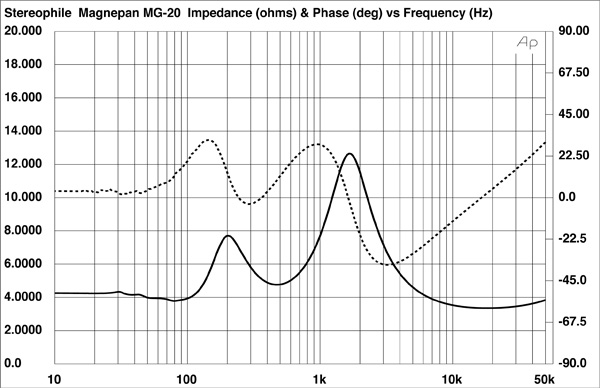
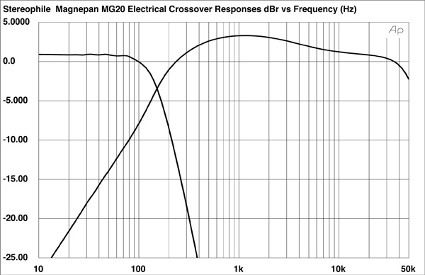
The humps at 200Hz and 1.7kHz in the impedance-magnitude trace are due to the crossover. Fig.2 shows the electrical responses of the external crossover filters: the woofer is rolled off above 100Hz with a third-order slope; the midrange unit has a 6dB slope, realized with a single series capacitor. (The midrange/ribbon crossover is in-circuit at all times; the decision to bi-amp or bi-wire only affects the integration of the woofer and midrange panels.)
The rather complicated traces in fig.3 show the responses of the three drive-units measured with the DRA Labs MLSSA system and a B&K 4006 microphone calibrated to be flat on-axis. Each trace is a composite of the driver's lower-frequency response, taken in the nearfield with the microphone capsule very close to the geometric center of the drive-unit, and the quasi-anechoic response taken at a distance of 50". Each of the panels has a similar characteristic when measured in this manner: there's a peak at the frequency of the panel's "drumhead" resonance, with a sloped-down response above it. The degree of the slope is partly a function of the distance between the panel and the microphone, because with drive-units this large, the assumption made in measuring the speaker—that the microphone is in the farfield—is no longer valid. The result is a proximity effect that affects the measured response and the tonal balance—again, see later.
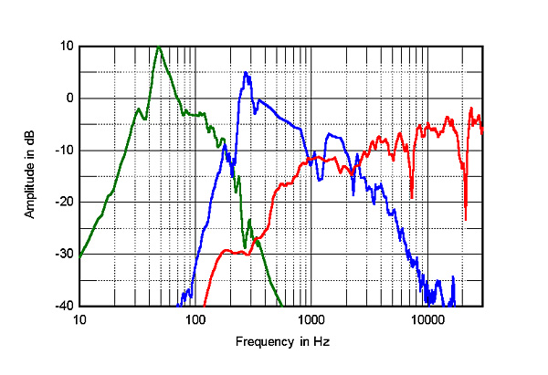
The ribbon's response is smooth in its passband—the notches at 2.4kHz, 7.2kHz, and 21kHz are specific to the microphone position, and are inconsequential. Note, however, the significant overlap between the ribbon and the midrange panels. This will make the MG-20 rather fussy when it comes to choosing the optimal lateral axis.
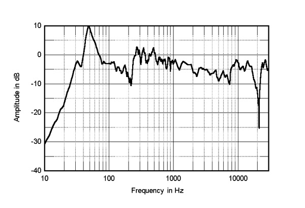
Fig.4 shows the overall response of the MG-20 on the ribbon axis at a 100" microphone distance, averaged across a 30° horizontal window. (The microphone was 40" from the floor, halfway up the speaker, but about a third of the way up the ribbon, which is mounted on the panel's upper section.) On the left of this graph is shown the complex sum—magnitude and phase—of the nearfield responses of the woofer and midrange panels. The integration between the two looks rather uneven in the graph; it actually sounds much better (measuring big panel speakers is not a task for the timid). The midrange is still rather elevated at the 100" microphone distance, which was the farthest back I could get in the Stereophile listening room. Remember, however, that DO did find this to be a persistent characteristic of the big Magnepan's sound. The mid-treble is also a little depressed—again, as might be expected from DO's auditioning notes.
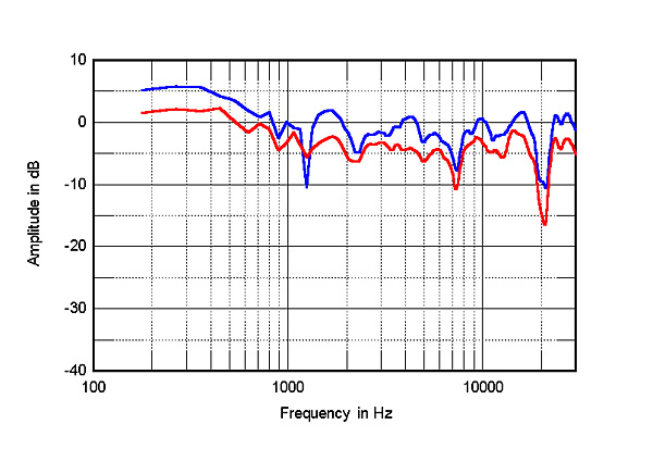
I next examined the proximity effect in my measurements. Fig.5 shows the MG-20's ribbon-axis response at two microphone distances: 50" (top trace) and 100" (bottom). Doubling the microphone distance drops the absolute level by an average of 3–4dB rather than the 6dB typical of a point-source speaker, confirming the MG-20's line-source behavior. More important, although there's slightly less of a midrange prominence to the balance at the greater microphone distance, it's still present. In all but enormous rooms where the listener can sit a long way away, the MG-20 will sound generous in this frequency region.
Vertically (not shown), the MG-20's balance changes little with listener height—again, this is a characteristic of line-source behavior. Horizontally, however, things are more difficult, due to the use of three side-by-side drive-units, crossover filters with relatively shallow slopes, and the significant degree of overlap between the ribbon and the midrange panel. Fig.6 shows just the differences in response as the listener moves to the side of the ribbon axis, with the changes off-axis on the tweeter side to the front of the graph. (Ignore the apparent peaks in this graph, which are due to the on-axis notches in fig.4 filling-in to the speaker's sides.) As can be seen, moving just 15° to either side of the tweeter results in a severe suckout in the mid-treble. The greatest lack of energy is on the ribbon side of the panel, which is why DO presumably found it best to have the ribbons on the inside edges of the stereo pair. Doing so will result in the side-wall reflection, which, having the most neutral sound-quality, will have the greatest influence on the speaker's perceived balance.
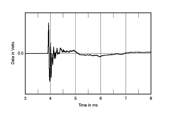
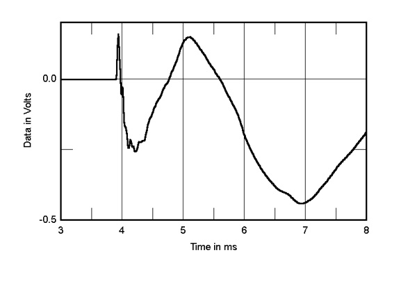
In the time domain, the MG-20's impulse response (fig.7) suggests that the speaker is not time-coherent—a surprising result, given that the drive-units are all in the same plane. The step response (fig.8) confirms this, as the three separate wavefront arrivals from each of the drive-units can be seen in this graph: the positive-going spike closest to the left-hand edge of the graph is the ribbon tweeter's output; the negative-going, slower-risetime pulse just after the 4 millisecond mark is the midrange panel's output; and the large, lazy, negative-going pulse after the 5.5ms mark is the woofer. I checked this by looking at the step response of each drive-unit driven on its own: both panels are connected with negative acoustic polarity, the tweeter with positive.
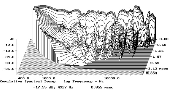
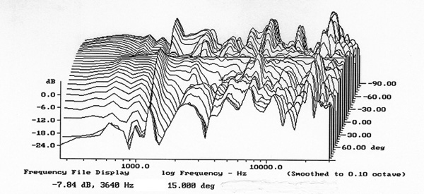
Finally, the cumulative spectral-decay, or waterfall, plot for the MG-20 (fig.9) may look a little hashy in the mid-treble, but is much better than is usually found in planar speakers, which tend to exhibit a trace of chaotic behavior. All in all, my measurements show a good correlation with the Magnepan's perceived balance, but perhaps underemphasize the design's positive attributes. In my own (mono) listening to the sample I measured, I was struck by the smoothness of its rather lower-midrange–dominant tonal balance.—John Atkinson