Intrigued by this 30-year-old D/A processor, I thought it would be interesting to run it through my standard set of measurements, using my Audio Precision SYS2722 system (see the January 2008 "As We See It").
The Digital Link's serial number on the pcb was 1172. Its single coaxial S/PDIF input would lock only to data sampled at 44.1 or 48kHz, an understandable limitation of its Yamaha S/PDIF receiver chip—back in 1989, there were no sources of data sampled with rates above 48kHz. A 1kHz digital signal at 0dBFS resulted in an output level of 3.04V into 100k ohms, which is 3.6dB higher than the CD standard's 2V. The analog outputs preserved absolute polarity (ie, were non-inverting), and the output impedance was a very low 1.3 ohms from 20Hz to 20kHz. (The PS Audio uses a high-performance Analog Devices AD847 op-amp chip for each output channel.)
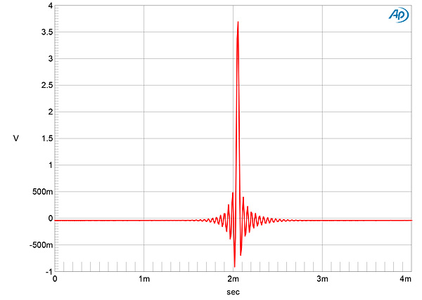
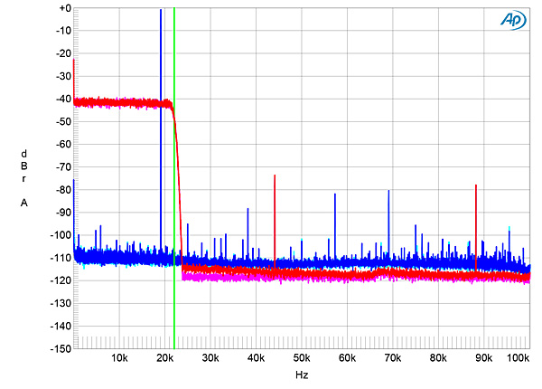
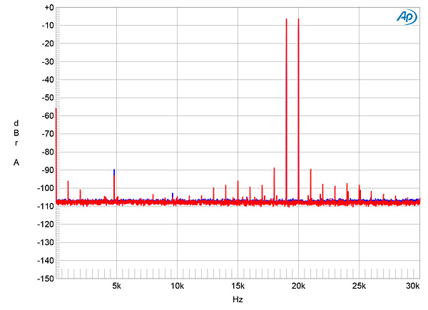
The Digital Link's impulse response with 44.1kHz data (fig.1) indicates that its reconstruction filter, implemented with a Yamaha YM3434 8x-oversampling chip, is a conventional linear-phase type, with a large amount of time-symmetrical ringing to either side of the single sample at 0dBFS. With 44.1kHz-sampled white noise (fig.2, red and magenta traces), the Link's response rolled off extremely sharply above 20kHz, reaching full stop-band suppression at 24kHz, a little above half the sample rate (vertical green line). An aliased image at 25kHz of a full-scale tone at 19.1kHz (blue and cyan traces) is suppressed by 95dB. Though the second, third, and fourth harmonics of the 19.1kHz tone are visible above the ultrasonic noise floor, these all lie below –80dB (0.01%). However, spurious tones at 44.1 and 88.2kHz can be seen in this graph.
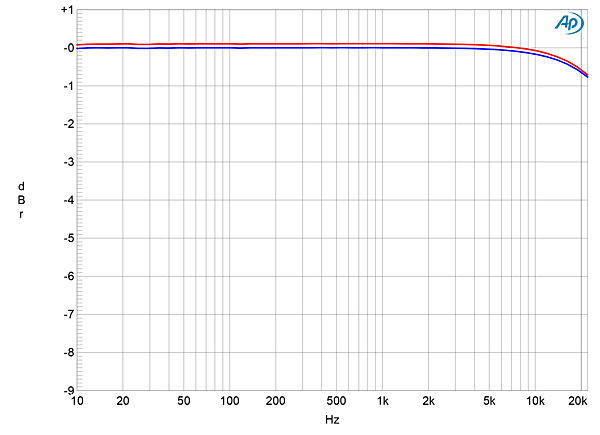
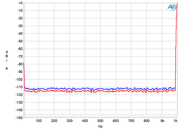
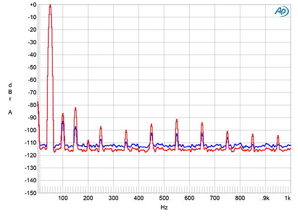
The Digital Link's frequency response with 44.1kHz data was down by 0.7dB at 20kHz (fig.3), and the two channels matched very closely. Channel separation was only moderate, at 70dB in both directions below 1kHz, decreasing at 20kHz to 44dB R–L and 58dB L–R. The low-frequency noise floor (fig.4) was free from any power-supply–related artifacts, but this might be because the random noise floor is relatively high in level, with individual components lying between –100 and –114dB. This suggests that the PSA's resolution is around 14 bits, which was confirmed when I examined the spectrum with a dithered 16-bit 1kHz tone at –90dBFS (fig.5). The noise in the right channel in this graph (red trace) is high and although it is lower in the left channel (blue), the second harmonic is were higher in level than the 1kHz fundamental tone.
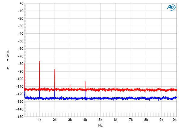
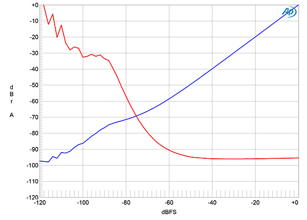
Of much greater concern in fig.5 is that while the data described a tone at –90dBFS, that tone was reproduced just below –70dBFS in the right channel (red trace) but at –113dBFS in the left channel (blue)! (I note that Herb Reichert was not impressed by the Digital Link's behavior with low-level information.) I therefore plotted how the output level varied with the level described by the data. You can see from the red trace in fig.6, which shows the right channel's linearity error, that the DAC's output level begins to deviate significantly from what it should be below –60dBFS, with a positive error that reaches 12dB at –90dBFS. By contrast, fig.7 shows the left channel's linearity error. Now, while the output starts to depart from the correct level below –60dBFS, the error is negative and reaches –13dB at –90dBFS.
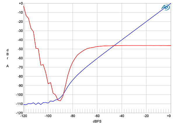
The Digital Link uses a Burr-Brown PCM-61P 18-bit DAC chip for each channel. According to the chip's datasheet, while Burr-Brown guaranteed that the chip as shipped to its customers met its specifications, there is a Most Significant Bit (MSB) adjustment, to minimize linearity error. All I can think of is that in the three decades since this sample of the Digital Link was manufactured, this adjustment drifted from what it should be and did so in different directions for the two channels.
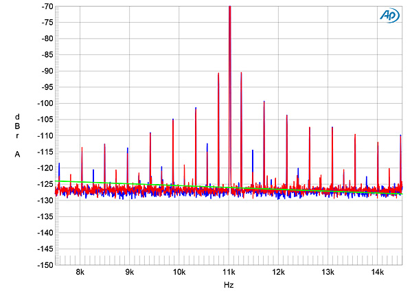
As suggested by fig.2, harmonic distortion was low in level (fig.8), though a little higher in the right channel (red trace) than in the left (blue). Intermodulation distortion was similarly low (fig.9), though the random noise floor again lies close to the 14-bit level in this graph. However, when I tested its rejection of word-clock jitter with 16-bit data, the PS Audio Digital Link stumbled again. The odd-order harmonics of the LSB-level, low-frequency squarewave were all significantly higher than the correct levels (the latter indicated by the sloping green line in fig.10).
Seeing how a 30-year-old D/A processor's measured performance stacked up against state-of-the-art modern DACs such as PS Audio's own PerfectWave DirectStream was an intriguing experiment. But I was disappointed by the Digital Link; it hasn't worn its years well.—John Atkinson