Sidebar 4: Measurements
I measured the Benchmark LA4's performance with my Audio Precision SYS2722 system (see the January 2008 "As We See It"). The gain for the balanced inputs to the balanced output with the volume control set to "+15" was exactly 15dB, and reducing the control to "0.0" resulted in a gain of 0dB—ie, the output voltage was the same as the input voltage. For the unbalanced inputs to the unbalanced output, the maximum gain was 5.25dB. Pressing the "–20" mute button on the touchscreen reduced the balanced gain by 20dB, the unbalanced gain by 10dB. The preamplifier preserved absolute polarity (ie, was noninverting) with both balanced and unbalanced inputs and outputs. (The XLR jacks are wired with pin 2 hot, the AES convention.)
The LA4's balanced input impedance was both usefully high and higher than the specified >50k ohms, measuring 80k ohms (40k ohms per phase) at 20Hz and 1kHz and still 75k ohms at 20kHz. The unbalanced input impedance was a little lower than specified but still high, at 37k ohms at 20Hz and 1kHz and 29k ohms at 20kHz. The balanced output impedance was a low 61.5 ohms, the unbalanced impedance 201 ohms, both values consistent across the audioband.
The preamplifier's frequency response in both balanced and unbalanced modes was flat from 10Hz to 200kHz both into the high 100k ohm load (fig.1, blue and red traces) and into 600 ohms (cyan, magenta). Fig.1 was taken with the LA4's volume control at its maximum setting; both the response and the superb channel matching were identical at lower settings of the control. Channel separation was simply superb, at >140dB, R–L, and >132dB, R–L, below 2kHz, respectively decreasing to 130dB and 112dB at 20kHz (not shown). The superb separation measurement is a testament to excellent circuit-board layout, something I have commented on before with Benchmark D/A processors.
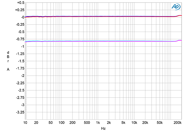
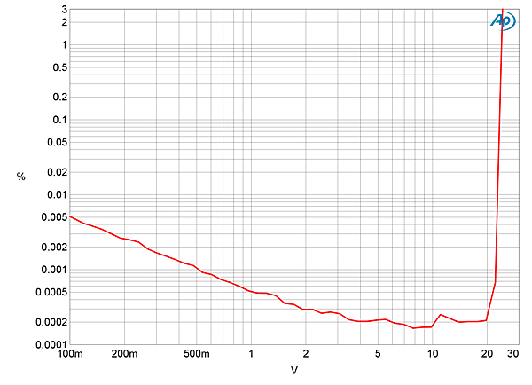
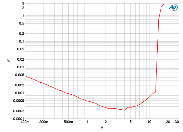
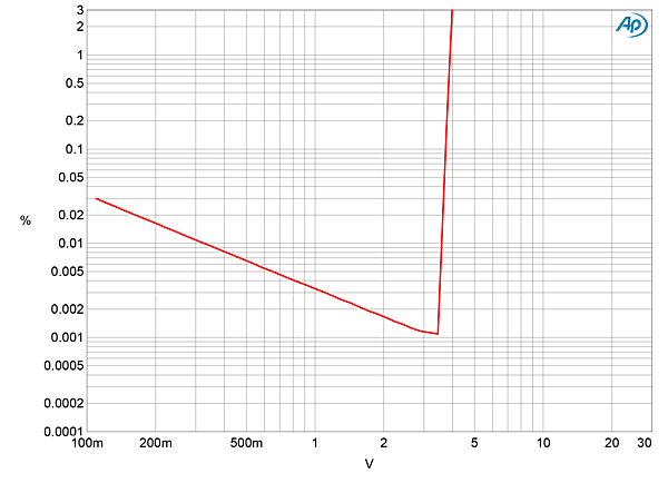
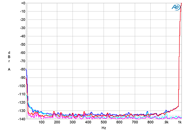 Fig.3 plots the percentage of THD+noise in the LA4's balanced output into 100k ohms. The THD+N rises below 8V output due to the fixed level of noise becoming an increasing percentage of the signal level. The LA4's balanced output doesn't clip (ie, when the THD+N reaches 1%) until a very high 24V. Reducing the load to a punishing 600 ohms reduced the maximum output level to 15V (fig.4), which is still much higher than will be needed to drive a power amplifier into clipping. The unbalanced output clipped at much lower output levels, 3.9V into 100k ohms (fig.5) and 2.9V into 600 ohms. Nevertheless, these lower maximum levels will be sufficient to drive amplifiers with single-ended inputs to their rated powers.
 I looked at the spectrum of the distortion at a similarly high output level (fig.7); while the second and third harmonics can be seen, these are still at astonishingly low levels: each harmonic is at or below –120dB (0.0001%) and is close to the residual level of these harmonics in my Audio Precision SYS2722's signal generator. The level of the noise floor might also be due to the SYS2722 A/D converter's self-noise. I repeated the spectral analysis, therefore, with a loan sample of Audio Precision's more-recent, higher-performance AP555x system that I am evaluating; the spectrum was identical, as it was when I reduced the load impedance to 600 ohms. The second harmonic was virtually absent when I drove the unbalanced output at 2V into 100k ohms; though the third harmonic was higher in level than it had been for balanced operation, it was still negligible, at –109dB in the right channel and –117dB in the left.
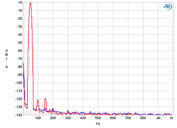
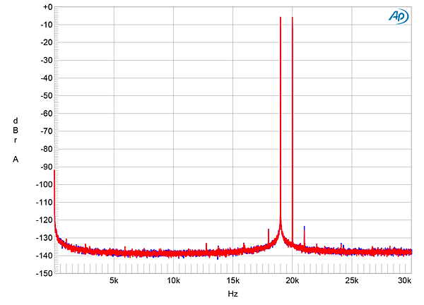
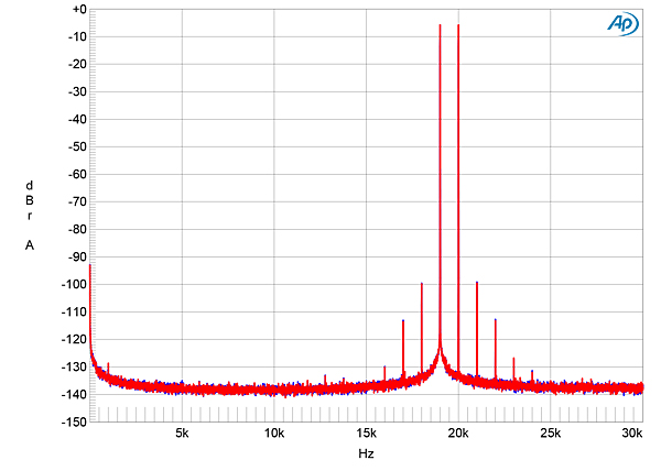
Fig.1 Benchmark LA4, balanced frequency response with volume control set to "+15" at 1V into: 100k ohms (left channel blue, right red), 600 ohms (left cyan, right magenta) (0.5dB/vertical div.).
From balanced inputs to balanced output, the Benchmark preamp offered extremely low noise, with virtually no power-supply–related spuriae in its output (fig.2). The wideband, unweighted signal/noise ratio, measured with the balanced input shorted to ground but the volume control set to its maximum, was 71.4dB, left, and 83.6dB, right, both ratios ref. 1V output. It is possible that with its very wide bandwidth, the LA4 was picking up some RF-related noise in my test lab. Restricting the measurement bandwidth to the audioband increased the S/N ratio to an astonishing 105.5dB for both channels, while switching an A-weighting filter into circuit further improved this ratio, to 108.7dB!
Fig.2 Benchmark LA4, balanced spectrum of 1kHz sinewave, DC–1kHz, at 1V into 100k ohms (left channel blue, right red) (linear frequency scale).
Fig.3 Benchmark LA4, balanced distortion (%) vs 1kHz output voltage into 100k ohms.
Fig.4 Benchmark LA4, unbalanced distortion (%) vs 1kHz output voltage into 100k ohms.
Fig.5 Benchmark LA4, unbalanced distortion (%) vs 1kHz output voltage into 600 ohms.
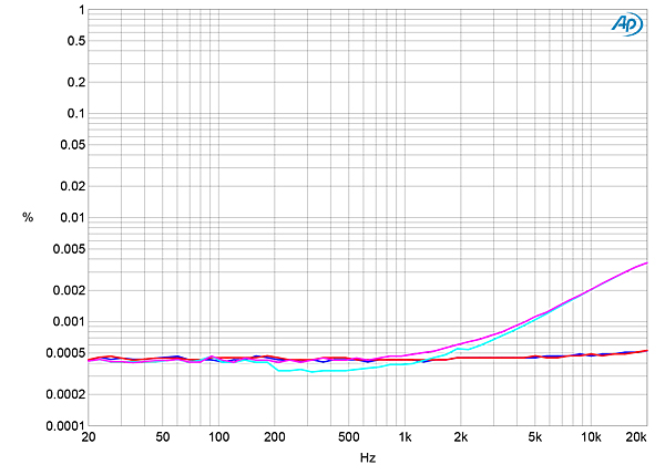
To be sure that the reading was not dominated by noise, I measured how the LA4's distortion changed with frequency at 5V, where figs.3 and 4 suggested that actual distortion was starting to rise above the low noise floor. The THD+N percentage was extremely low throughout the audioband into 100k ohms (fig.6, blue and red traces). Into 600 ohms (cyan, magenta traces), though the THD+N percentage rose in the top audio octaves, it was still just 0.0045% at 20kHz.
Fig.6 Benchmark LA4, THD+N (%) vs frequency (Hz) at 5V into 100k ohms (left channel blue, right red) and 600 ohms (left cyan, right magenta).
Fig.7 Benchmark LA4, Benchmark LA4, balanced spectrum of 50Hz sinewave, DC–1kHz, at 5V into 100k ohms (left channel blue, right red; linear frequency scale)..
Tested for intermodulation distortion in balanced mode with an equal mix of 19 and 20kHz tones at peak level of 5V, the second-order difference product at 1kHz was effectively absent, and the higher-order products all lay at or below –114dB (0.0002%, fig.8). These products rose to –100dB (0.001%) at 5V into 600 ohms (fig.9), correlating with the reduction in high-frequency linearity into this impedance seen in fig.5, but are still very low in absolute terms.
Fig.8 Benchmark LA4, balanced HF intermodulation spectrum, DC–30kHz, 19+20kHz at 5V into 100k ohms (left channel blue, right red; linear frequency scale).
Fig.9 Benchmark LA4, balanced HF intermodulation spectrum, DC–30kHz, 19+20kHz at 5V into 600 ohms (left channel blue, right red; linear frequency scale).
Benchmark's LA4 is the widest-bandwidth, widest-dynamic-range, lowest-noise, lowest-distortion preamplifier I have encountered.—John Atkinson


