Sidebar 3: Measurements
 I performed a full set of measurements on the AVM Evolution AS 5.3 with my Audio Precision SYS2722 system. I installed the AVM RC X app on my iPad mini, and when I connected the AVM's Ethernet port to my router, the app asked if I wanted to update the amplifier's software. After the update, the AS 5.3 was running firmware version 1.0.117.
As the AVM uses a class-D output stage that emits relatively high levels of ultrasoic noise, which would drive my analyzer's input into slew-rate limiting, I inserted an Audio Precision AUX-0025 passive low-pass filter between the test load and the analyzer. This filter mitigates noise above 80kHz and eliminates noise above 200kHz; without the filter, I measured 369mV of ultrasonic noise with a center frequency of 449kHz in the amplifier's speaker outputs. I used this filter for all the power amplifier tests other than the frequency response.
I preconditioned the amplifier by running it at a moderate power into 8 ohms for 30 minutes before starting the testing.
I looked first at the AVM AS 5.3's balanced and single-ended line-level inputs. The AS 5.3 preserved absolute polarity, ie, was noninverting, at the loudspeaker, single-ended LINE and PRE, balanced PRE, and headphone outputs. The unbalanced line input impedance was close to the specified 50k ohms, at 47.5k ohms at 20Hz and 1kHz, dropping to 23.6k ohms at the top of the audioband. The balanced input impedance was 31k ohms from 20Hz to 20kHz; the specified input impedance is 40k ohms. Other than the step from the maximum of "99.5" to "99," which reduced the level by 0.5dB, the volume control operated in accurate 1dB steps down to "79." With the volume control set to its maximum, the voltage gain at 1kHz with both types of inputs was 48.4dB from the loudspeaker output into 8 ohms, 24.5dB from the headphone output into 100k ohms, 18.6dB from both PRE outputs, and 0dB from the LINE output. The volume control and Mute button didn't operate with the LINE output.
I performed a full set of measurements on the AVM Evolution AS 5.3 with my Audio Precision SYS2722 system. I installed the AVM RC X app on my iPad mini, and when I connected the AVM's Ethernet port to my router, the app asked if I wanted to update the amplifier's software. After the update, the AS 5.3 was running firmware version 1.0.117.
As the AVM uses a class-D output stage that emits relatively high levels of ultrasoic noise, which would drive my analyzer's input into slew-rate limiting, I inserted an Audio Precision AUX-0025 passive low-pass filter between the test load and the analyzer. This filter mitigates noise above 80kHz and eliminates noise above 200kHz; without the filter, I measured 369mV of ultrasonic noise with a center frequency of 449kHz in the amplifier's speaker outputs. I used this filter for all the power amplifier tests other than the frequency response.
I preconditioned the amplifier by running it at a moderate power into 8 ohms for 30 minutes before starting the testing.
I looked first at the AVM AS 5.3's balanced and single-ended line-level inputs. The AS 5.3 preserved absolute polarity, ie, was noninverting, at the loudspeaker, single-ended LINE and PRE, balanced PRE, and headphone outputs. The unbalanced line input impedance was close to the specified 50k ohms, at 47.5k ohms at 20Hz and 1kHz, dropping to 23.6k ohms at the top of the audioband. The balanced input impedance was 31k ohms from 20Hz to 20kHz; the specified input impedance is 40k ohms. Other than the step from the maximum of "99.5" to "99," which reduced the level by 0.5dB, the volume control operated in accurate 1dB steps down to "79." With the volume control set to its maximum, the voltage gain at 1kHz with both types of inputs was 48.4dB from the loudspeaker output into 8 ohms, 24.5dB from the headphone output into 100k ohms, 18.6dB from both PRE outputs, and 0dB from the LINE output. The volume control and Mute button didn't operate with the LINE output.
Channel separation depended on the setting of the volume control. With the control set to the maximum the crosstalk lay at –50dB in both directions below 2kHz. Setting the control to –20dB and increasing the level of the input signal by 20dB increased the channel separation below 2kHz by 20dB; it was 50dB at the top of the audioband.
I performed a full set of measurements on the AVM Evolution AS 5.3 with my Audio Precision SYS2722 system. I installed the AVM RC X app on my iPad mini, and when I connected the AVM's Ethernet port to my router, the app asked if I wanted to update the amplifier's software. After the update, the AS 5.3 was running firmware version 1.0.117.
As the AVM uses a class-D output stage that emits relatively high levels of ultrasoic noise, which would drive my analyzer's input into slew-rate limiting, I inserted an Audio Precision AUX-0025 passive low-pass filter between the test load and the analyzer. This filter mitigates noise above 80kHz and eliminates noise above 200kHz; without the filter, I measured 369mV of ultrasonic noise with a center frequency of 449kHz in the amplifier's speaker outputs. I used this filter for all the power amplifier tests other than the frequency response.
I preconditioned the amplifier by running it at a moderate power into 8 ohms for 30 minutes before starting the testing.
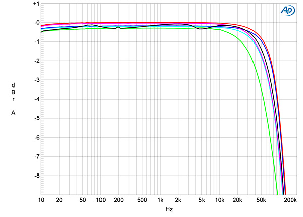
Fig.1 AVM AS 5.3, line input, frequency response at 2.83V into: simulated loudspeaker load (gray), 8 ohms (left channel blue, right red), 4 ohms (left cyan, right magenta), 2 ohms (green) (1dB/vertical div.).
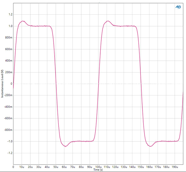
Fig.2 AVM AS 5.3, line input, small-signal, 10kHz squarewave into 8 ohms.
The single-ended PRE and LINE output impedances were a usefully low 47 ohms from 20Hz to 20kHz; the balanced PRE output impedance was 93.5 ohms across the audioband; and the headphone output impedance was a low 25 ohms from 20Hz to 20kHz. The loudspeaker output impedance was very low, at 0.045 ohm at 20Hz and 1kHz, rising slightly to 0.1 ohm at 20kHz. The modulation of the AVM AS 5.3's frequency response due to the Ohm's law interaction between this impedance and the impedance of our standard simulated loudspeaker was therefore negligible (fig.1, gray trace). The amplifier's response into resistive loads with the output set to Linear, which bypasses the tone and loudness controls, was flat in the audioband and –3dB at 85kHz into 8 ohms (blue and red traces). Both the very close channel balance and the overall response were preserved at lower settings of the volume control and with both the balanced and unbalanced inputs and the headphone outputs. The response from the headphone output was down by 2dB at 200kHz. There was a single cycle of overshoot and ringing on the AVM AS 5.3's reproduction of a 10kHz squarewave into 8 ohms (fig.2).
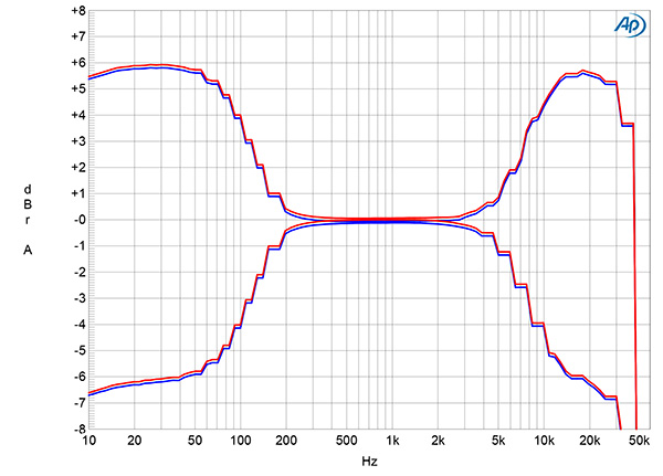
Fig.3 AVM AS 5.3, line input, frequency response into 8 ohms with the treble and bass controls set to the maximum and minimum (left channel blue, right red) (2dB/vertical div.).
With the Loudness control off and the Tone controls activated, the treble and bass controls offered a maximum boost of 6dB and a maximum cut of 7dB above 10kHz and below 100Hz (fig.3). The traces in this graph rapidly roll off above 42kHz, which suggests that the analog input is digitized with a sample rate of 96kHz when the controls are activated.
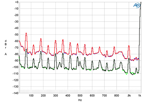
Fig.4 AVM AS 5.3, line input, spectrum of 1kHz sinewave, DC–1kHz, at 1Wpc into 8 ohms with volume control set to the maximum (left channel blue, right red) and to –20dB (left green, right gray) (linear frequency scale).
The S/N ratio also depended on the volume control setting. With the volume control set to its maximum, the single-ended line inputs shorted to ground, and the Audio Precision ultrasonic filter in place, the wideband, unweighted S/N ratio at the loudspeaker outputs was a poor 41.4dB (average of both channels), ref. 2.83V, which is equivalent to 1W into 8 ohms. This ratio improved to 50.4dB when the measurement bandwidth was restricted to the audioband and to 55.4dB when A-weighted. Lowering the volume control by 20dB increased all these ratios by 18dB. The effect of the volume control can be seen in the spectra of the AVM AS 5.3's low-frequency noisefloor at 1Wpc into 8 ohms. The levels of random noise and power supply–related spuriae with the volume control set to its maximum (fig.4, red and blue traces) dropped by 20dB when I set the volume control to –20dB and increased the level of the input signal so that the output was the same 1Wpc into 8 ohms (green, gray traces).
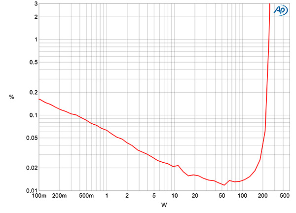
Fig.5 AVM AS 5.3, line input, THD+N (%) vs 1kHz continuous output power into 8 ohms.
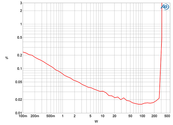
Fig.6 AVM AS 5.3, line input, THD+N (%) vs 1kHz continuous output power into 4 ohms.
To minimize the effect of noise on the results, I kept the volume control set to –20dB for the subsequent tests. AVM specifies the AS 5.3's maximum power as 180Wpc into 8 ohms (22.55dBW) and 350Wpc into 4 ohms (22.4dBW). Figs.5 and 6 respectively plot how the THD+noise percentage in the AVM AS 5.3's output varies with power into 8 ohms and 4 ohms with both channels driven. Stereophile defines clipping as when the THD+N reaches 1%. The AVM AS 5.3 clipped at 245Wpc into 8 ohms (23.9dBW) and at 310Wpc into 4 ohms (21.9dBW). The FTC's updated "Amplifier Rule" states that maximum power should also be assessed at frequencies other than 1kHz. I therefore repeated the power test with a 20kHz signal. The amplifier clipped at an impressive 300Wpc into 8 ohms at this frequency (24.8dBW).
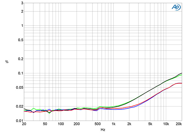
Fig.7 AVM AS 5.3, line input, THD+N (%) vs frequency at 20V into 8 ohms (left channel blue, right red) and 4 ohms (left green, right gray).
Fig.7 shows how the AVM AS 5.3's THD+N percentage changed with frequency at 20V, which is equivalent to 50W into 8 ohms (blue, red traces) and 100W into 4 ohms (green, gray traces). The distortion+noise at low and medium frequencies into both loads is very low, though there is the usual rise in the top audio octaves due to the circuit's limited open-loop bandwidth. (There is less corrective negative feedback available as the frequency increases.)
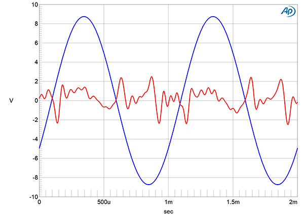
Fig.8 AVM AS 5.3, line input, 1kHz waveform at 100W into 4 ohms, 0.02% THD+N (blue); distortion and noise waveform with fundamental notched out (red, not to scale).
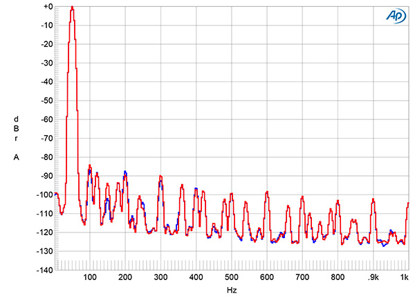
Fig.9 AVM AS 5.3, line input, spectrum of 50Hz sinewave, DC–1kHz, at 50Wpc into 8 ohms (left channel blue, right red, linear frequency scale).
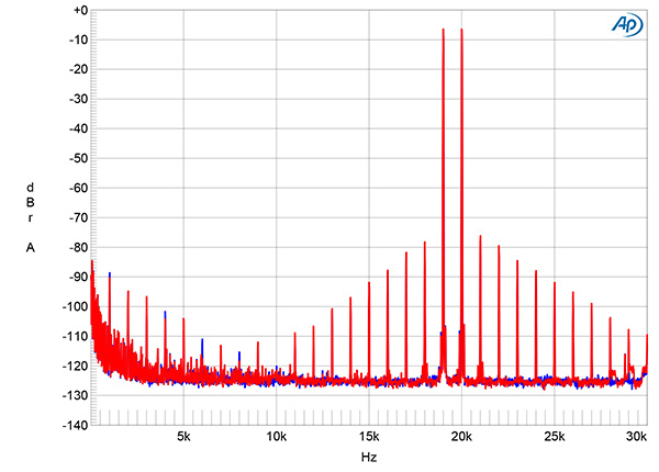
Fig.10 AVM AS 5.3, line input, HF intermodulation spectrum, DC–30kHz, 19+20kHz at 100Wpc peak into 4 ohms (left channel blue, right red, linear frequency scale).
The distortion signature was a mix of low-order harmonics (fig.8), with the second, third, and fourth harmonics all close to –90dB (0.003%) at 50W into 8 ohms (fig.9). Even at the same peak voltage into 4 ohms, intermodulation distortion with an equal mix of 19kHz and 20kHz tones was low in level (fig.10). The difference tone at 1kHz lay at –89dB (0.003%); though the higher-order products are 10dB higher in level, this is still low in absolute terms.—John Atkinson


