I measured the performance of the Audio-GD Vacuum HE1 XLR with my Audio Precision SYS2722 system, checking some of the results with the magazine's APx500 analyzer. Although this preamplifier has both balanced and single-ended inputs and outputs, HR told me he exclusively used the single-ended input and output so he could use the same unbalanced interconnects with the HE1 XLR that he used with his other preamplifiers. I focused primarily on the preamp's single-ended performance, therefore.
The HE1 XLR preserved absolute polarity (ie, was noninverting) with all combinations of inputs and outputs. (The XLR jacks are wired with pin 2 positive.) The maximum gain was 11.05dB for the single-ended and balanced inputs and single-ended outputs, 5.05dB for the balanced inputs at both output types. The volume control operated with approximate 0.8dB steps at the top of its range, 0.5dB steps at lower settings. HR told me that the maximum volume control setting he used was "62," out of an indicated "99." In addition to testing with the volume control set to "99," I did some tests with it set to "83" (unity gain) and "60" (–26.15dB).
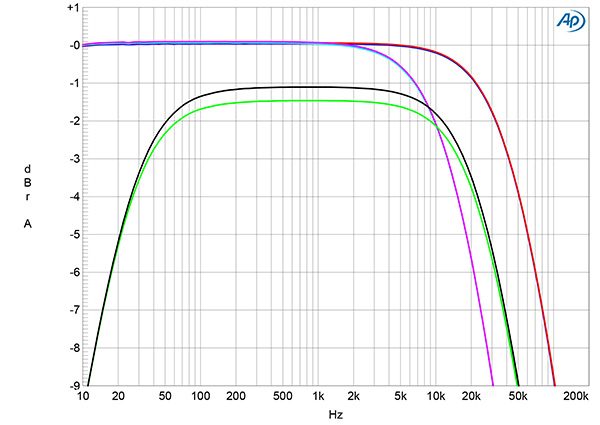
The single-ended input impedance was a very high 85k ohms at 20Hz and 1kHz and 32.7k ohms at 20kHz. The balanced input impedance was twice these values, as expected. The preamplifier's single-ended output impedance was 1644 ohms at 20Hz, 806 ohms at 1kHz, and 804 ohms at 20kHz. The balanced output impedance was 1806 ohms at 20Hz and 1047 ohms at 1kHz and 20kHz. The preamplifier's output at 20kHz varied with the setting of the volume control. With it set to the maximum (fig.1, cyan and magenta traces), the response was down by 5.5dB at 20kHz. With it set to "60," the 20kHz output (blue and red traces) was down by 0.9dB. These two sets of responses were taken into the high 100k ohms load; into 600 ohms (green and gray traces, offset by –1dB for clarity), the low frequencies rolled off, reaching –5dB at 20Hz. The channel matching was very close at all the volume control settings I measured.
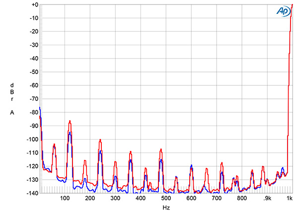
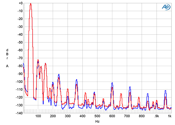
The Audio-GD preamp's channel separation was excellent, at >95dB across the audioband (not shown). With the single-ended input shorted to ground and the volume control set to "99," the wideband, unweighted signal/noise ratio, ref. 1V output from both output types, was 64.6dB in both channels. Restricting the measurement bandwidth to the audioband didn't increase the S/N ratio, though switching an A-weighting filter into circuit improved the ratio to 78.7dB. Fig.2 shows the low-frequency spectrum ref. 1V with the volume control set to "60." While the level of low-frequency random noise is low, AC-related spuriae are present, with the highest in level, at 120Hz, close to –90dB in both channels. Absolute spuriae levels were unaffected by the volume control setting, indicating that they are introduced after the control.
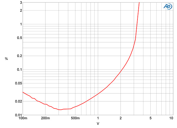
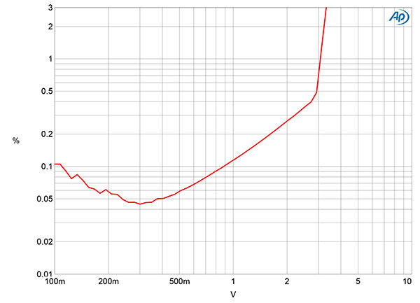
Fig.3 shows how the THD+noise percentage varied with voltage with the single-ended output driving 100k ohms. The downward slope of the trace below 500mV is due to the reading being dominated by noise. Actual distortion starts to rise above the noisefloor above that voltage, and the THD+N reaches 1%-our usual definition of clipping-at 3.3V into 100k ohms. The balanced output clipped at the same voltage into 100k ohms, while the single-ended output clipped at 3.1V into 10k ohms (fig.4). The Audio-GD's maximum output into 600 ohms was just 100mV (not shown).

Fig.5 shows how the THD+N percentage changes with frequency at 1V into 100k ohms and 10k ohms. It doesn't change significantly with frequency but, as seen in fig.4, the distortion is higher into 10k ohms than into 100k ohms.
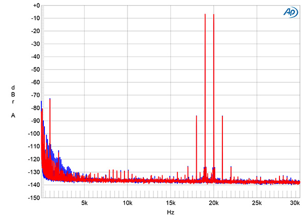
The Audio-GD's distortion signature (fig.6) is dominated by the second and third harmonics, these lying, respectively, at –72dB (0.025%) and –77dB (0.014%) ref. 1V into 100k ohms. Intermodulation distortion with an equal mix of 19kHz and 20kHz tones at a peak level of 1V into 100k ohms (fig.7) was also low in level, the second-order difference product at 1kHz lying at –73dB (0.022%).
Overall, the Audio-GD Vacuum HE1 XLR's measured performance was very good, especially for a tubed design, but it shouldn't be used with power amplifiers that have an input impedance of 10k ohms or lower. Also note that it offers its most extended high-frequency response at volume control settings of "60" and below on the front-panel display.—John Atkinson


