Sidebar 3: Measurements
I performed the measurements of the AirTight ATM-1E with my Audio Precision SYS2722 system. Before I started the testing, I followed the instructions in the manual to optimize the bias for the four EL34 output tubes. There are two output transformer taps, labeled High and Low instead of the usual 8 ohms and 4 ohms. I performed a complete set of measurements at each of the taps. The attenuation controls (one for each channel) were set to the minimum for the tests, ie, to the highest gain.
The ATM-1E's voltage gain into 8 ohms was 29.4dB from the High tap and 26.9dB from the Low tap. The amplifier preserved absolute polarity, ie, was noninverting, from both taps.

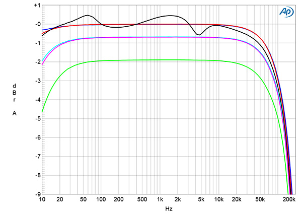
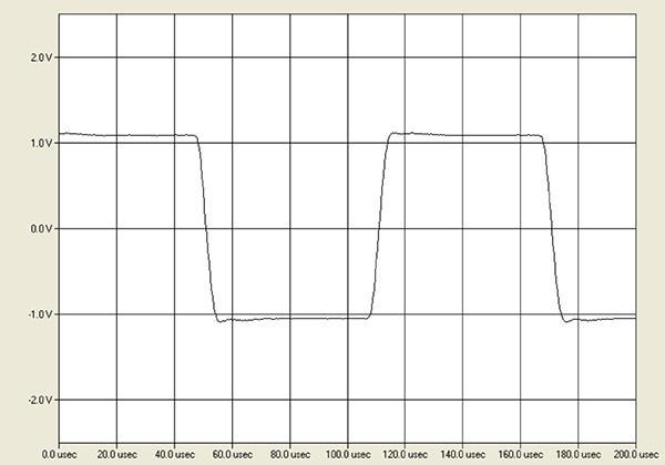
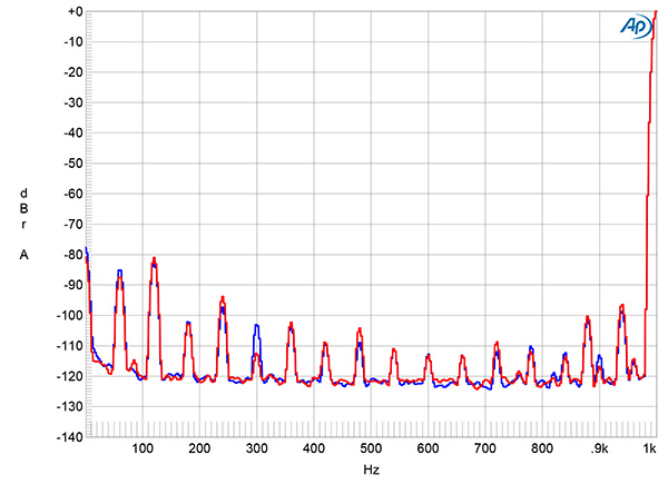
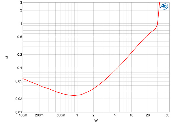
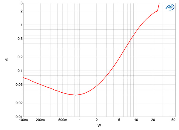
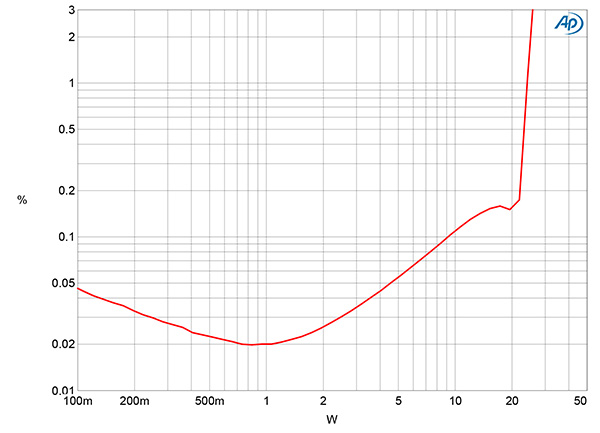
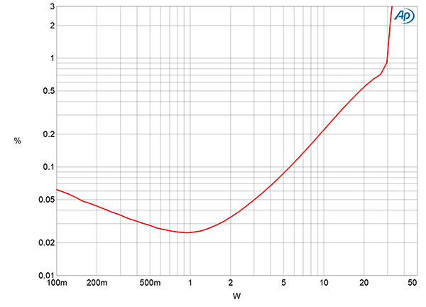
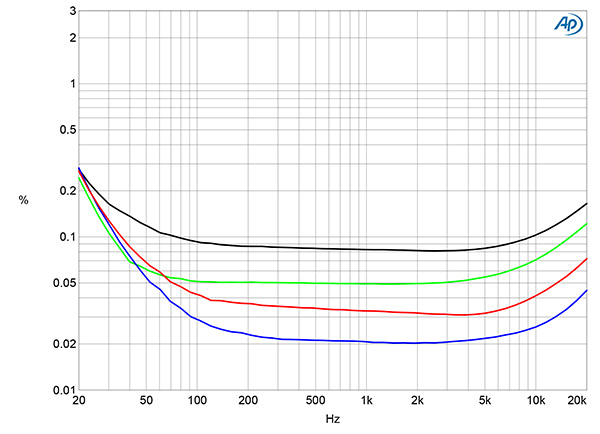
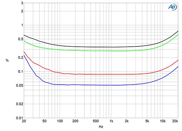
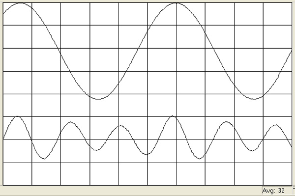
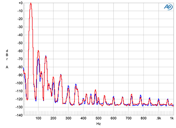
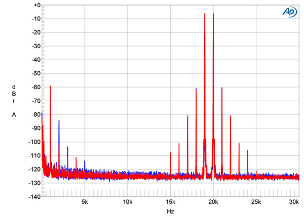
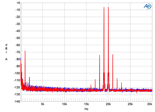
Fig.1 Air Tight ATM-1E, High output tap, frequency response at 2.83V into: simulated loudspeaker load (gray), 8 ohms (left channel blue, right red), 4 ohms (left cyan, right magenta), and 2 ohms (green) (1dB/vertical div.).
Fig.2 Air Tight ATM-1E, Low output tap, frequency response at 2.83V into: simulated loudspeaker load (gray), 8 ohms (left channel blue, right red), 4 ohms (left cyan, right magenta), and 2 ohms (green) (1dB/vertical div.).
The AirTight's single-ended input impedance was 78k ohms at 1kHz, dropping to a still-high 58k ohms at 20kHz. The source impedance from the High output tap was lower than I often find with tube amplifiers, at 1.85 ohms at 20Hz, 1.28 ohms at 1kHz, and 1.3 ohms at 20kHz. The impedances from the Low output tap were close to half these values, at 0.93 ohms at 20Hz, 0.69 ohms at 1kHz, and 0.71 ohms at 20kHz. The modulation of the frequency response of our standard simulated loudspeaker from the High tap was relatively low in amplitude, at ±0.90dB (fig.1, gray trace). The variation from the Low tap was half that, at ±0.45dB (fig.2, gray trace). The response into resistive loads (fig.1, blue, red, cyan, magenta, and green traces) was flat within the audioband and down by 3dB close to 100kHz, with superb channel matching.
Fig.3 Air Tight ATM-1E, High output tap, small-signal 10kHz squarewave into 8 ohms.
Fig.3 shows the waveform of a small-signal 10kHz squarewave at 10kHz. With the amplifier's wide small-signal bandwidth, the risetimes are very short and, commendably, there is no ringing and only a slight hint of overshoot.
Fig.4 Air Tight ATM-1E, High output tap, spectrum of 1kHz sinewave, DC–1kHz, at 1Wpc into 8 ohms (left channel blue, right red) (linear frequency scale).
The AirTight's channel separation (not shown) was very good, at >80dB in both directions below 1kHz and still 60dB at the top of the audioband. The unweighted, wideband signal/noise ratio (ref. 1W into 8 ohms) taken from the High taps with the inputs shorted to ground was a good 77dB in both channels. This ratio improved only slightly when the measurement bandwidth was restricted to 22Hz–22kHz, and to 88.6dB when A-weighted. With the lower gain from the Low taps, these S/N ratios were all 2–3dB higher. Spectral analysis of the low-frequency noisefloor while the AirTight's High taps drove a 1kHz tone at 1Wpc into 8 ohms (fig.4) revealed a low level of random noise in both channels. While AC supply–related spuriae were present at 60Hz and its odd- and even-order harmonics, these all lay at or below –80dB (0.01%).
Fig.5 Air Tight ATM-1E, High output tap, distortion (%) vs 1kHz continuous output power into 8 ohms.
Fig.6 Air Tight ATM-1E, High output tap, distortion (%) vs 1kHz continuous output power into 4 ohms.
Fig.7 Air Tight ATM-1E, Low output tap, distortion (%) vs 1kHz continuous output power into 8 ohms.
Fig.8 Air Tight ATM-1E, Low output tap, distortion (%) vs 1kHz continuous output power into 4 ohms.
The ATM-1E's maximum power is specified as 35Wpc (15.3dBW) at 5% THD, though no load impedance is mentioned. Looking first at the High output tap, with our usual definition of clipping (when the THD+noise reaches 1%), I measured a clipping power of 30.3Wpc with both channels driven into 8 ohms (14.8dBW, fig.5). Relaxing the clipping definition to 3% THD+N gave a maximum power of 33Wpc (15.2dBW). Less power was available from the High tap into 4 ohms: 12Wpc at 1% THD+N (7.8dBW) and 26Wpc at 3% THD+N (17.5dBW, fig.6). The Low tap clipped at 24Wpc into 8 ohms at 3% THD+N (13.8dBW, fig.7), and at 30Wpc at 1% THD+N (11.75dBW) and 32Wpc (12dBW) at 3% THD+N into 4 ohms (fig.8).
Fig.9 Air Tight ATM-1E, Low output tap, THD+N (%) vs frequency at 3.5V into: 8 ohms (left channel blue, right red), 4 ohms (left green, right gray).
Fig.10 Air Tight ATM-1E, High output tap, THD+N (%) vs frequency at 4.85V into: 8 ohms (left channel blue, right red), 4 ohms (left green, right gray).
The shape of the traces in figs.5–8 suggests that the circuit features a limited amount of loop negative feedback, though the distortion is quite low at moderate powers. Fig.9 shows how the percentage of THD+N in both channels varied with frequency with the Low transformer tap driving 8 ohms (blue and red traces) and 4 ohms (green and gray traces) at 3.5V. The THD+N is very low into 8 ohms, with only a slight rise in the top octave. There is a larger rise in distortion in the low bass, presumably due to the output transformer cores starting to saturate. Even so, the distortion is low in absolute terms; these are high-quality transformers. At the same input voltage, which resulted in a slightly higher output voltage, the High tap gave higher THD+N into both 4 ohms (fig.10, green and gray traces) and 8 ohms (blue and red traces). As expected, this tap is best suited for loudspeakers having high impedances.
Fig.11 Air Tight ATM-1E, High output tap, left channel, 1kHz waveform at 4.5W into 8 ohms, 0.08% THD+N (top); distortion and noise waveform with fundamental notched out (bottom, not to scale).
Fig.12 Air Tight ATM-1E, High output tap, spectrum of 50Hz sinewave, DC–1kHz, at 3Wpc into 8 ohms (left channel blue, right red; linear frequency scale).
The left channel's distortion waveform (fig.11) was predominantly the subjectively innocuous third harmonic, though the similarly innocuous second harmonic was highest in level in the right channel (fig.12) This suggests that the output tubes are not as well-matched in the right channel as they are in the left. (In a push-pull circuit, having the active devices perfectly matched eliminates even-order distortion.)
Fig.13 Air Tight ATM-1E, High output tap, HF intermodulation spectrum, DC–30kHz, 19+20kHz at 6Wpc peak into 4 ohms (left channel blue, right red; linear frequency scale).
Fig.14 Air Tight ATM-1E, High output tap, HF intermodulation spectrum, DC–30kHz, 19+20kHz at 6Wpc peak into 4 ohms (left channel blue, right red; linear frequency scale).
However, intermodulation distortion at high frequencies was relatively low in level, even with the High output taps driving an equal mix of 19 and 20kHz tones at 6Wpc peak into 4 ohms (fig.13). Both the 1kHz difference product and the higher-order products at 18 and 21kHz lay at –60dB (0.1%). At the same output voltage into 8 ohms (fig.14), the difference product was 10dB lower in level than it had been into 4 ohms, and the higher-order products were 15dB lower.
I was impressed by the AirTight ATM-1E's measured behavior. It performed better than AirTight's similar-looking ATM-1S that Art Dudley reviewed in November 2014, which also used a pair of EL34 output tubes for each channel. The new amplifier has less noise and distortion, a wider small-signal bandwidth, and offers usefully lower source impedances from both of its output transformer taps than the earlier amplifier with its single tap.—John Atkinson


