| Columns Retired Columns & Blogs |
Aesthetix Atlas power amplifier Measurements
Sidebar 3: Measurements
I examined the Aesthetix Atlas's measured behavior using mainly Stereophile's loan sample of the top-of-the-line Audio Precision SYS2722 system (see the January 2008 "As We See It" and www.ap.com); for some tests, I also used my vintage Audio Precision System One Dual Domain.
Before I test an amplifier, I run it for 60 minutes at one-third its specified power into 8 ohms. Thermally, this is the worst case for an amplifier with a class-B or -AB output stage, and this preconditioning taxes the amplifier's ability to dissipate waste heat. The Atlas's grilles above its internal heatsinks were just too hot to touch after 60 minutes, and the front panel was warm, suggesting its heatsinking is adequate for its power level.
The Atlas's voltage gain into 8 ohms was the same for balanced and unbalanced drive, at 25dB, which is lower than normal. Both inputs preserved absolute polarity (ie, were non-inverting), the XLR jacks being wired with pin 2 hot. Specified at a very high 470k ohms for the unbalanced input and twice that for the balanced, the amplifier's input impedances were at least those values at low and midrange frequencies, dropping slightly but inconsequentially at 20kHz. (With such high impedances, there is inevitably a large error in measuring the exact figure.) The Crossover inputs behaved identically to the main inputs in these respects.
The output impedance was relatively high for a design with a solid-state output stage, at 0.34 ohm at low and middle frequencies, rising very slightly to 0.36 ohm at 20kHz. As a result, the changes in the amplifier's amplitude response, due to the interaction of this impedance with that of our standard simulated loudspeaker (fig.1, gray trace), reached ±0.24dB, which will be just audible. Fig.1 also shows a slight (0.1dB) channel imbalance that appears to be due to the left channel (blue, cyan traces) having a slightly higher output impedance than the right (red, magenta traces). But the bandwidth was wide into all loads, with a –3dB point of 160kHz into 8 ohms, which results in a nicely square 10kHz squarewave (fig.2).
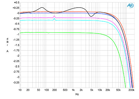
Fig.1 Aesthetix Atlas, frequency response at 2.83V into: simulated loudspeaker load (gray), 8 ohms (left channel blue, right red), 4 ohms (left cyan, right magenta), 2 ohms (green). (0.25dB/vertical div.)
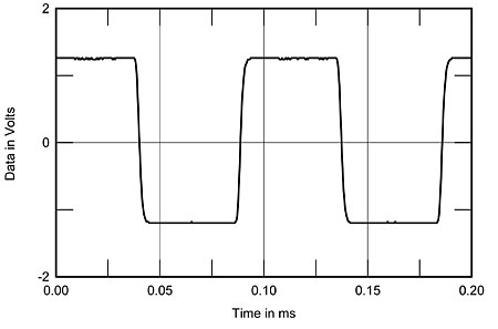
Fig.2 Aesthetix Atlas, small-signal 10kHz squarewave into 8 ohms.
Fig.3 shows the Atlas's frequency response via its Crossover inputs, with the Frequency control set to Off (top pair of traces below 200Hz), and to all settings between 40 and 200Hz. In each case, the –3dB point corresponds fairly closely to the nominal frequency chosen and in all cases, the ultimate rolloff is a gentle 6dB/octave. Channel separation (not shown) was superb, at better than 110dB below 1kHz, and still 89dB in both directions at 20kHz. The unweighted, wideband signal/noise ratio (ref. 1W into 8 ohms) was an excellent 85dB in the right channel but only 76.75dB in the left, the latter perhaps due to a noisier input-stage tube. Restricting the measurement bandwidth to the audioband gave almost identical results of 89dB left and 90dB right, with an A-weighting filter actually giving a higher result: 96.9dB in the left channel compared with 94.1dB in the right.
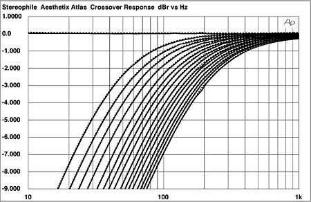
Fig.3 Aesthetix Atlas, Crossover input, frequency response at 2.83V into 8 ohms with control set to (from left to right): Off, 40Hz, 50Hz, 60Hz, 70Hz, 80Hz, 90Hz, 100Hz, 110Hz, 125Hz, 135Hz, 145Hz, 155Hz, 170Hz, 180Hz, 190Hz, 200Hz (1dB/vertical div.).
I plotted how the Atlas's THD+noise percentage varied with output power using the less-noisy right channel, so that the result wouldn't be obscured by noise at low powers. And at low powers into both 8 and 4 ohms (fig.4, bottom two traces below 10W), the THD+N was indeed low. As can be seen from this graph, however, it rose linearly with increasing power and reached approximately 0.13% before actual clipping, which suggests a low or zero degree of loop negative feedback. It was also significantly higher into 2 ohms (fig.4, top trace below 70W). With clipping defined as 1% THD, the Atlas comfortably exceeded its specified output power with both channels driven: fig.4 shows that it clipped at 318W into 8 ohms (25dBW), 535W into 4 ohms (24.3dBW), and, with one channel driven, at 760W into 2 ohms (22.8dBW).
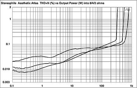
Fig.4 Aesthetix Atlas, distortion (%) vs 1kHz continuous output power into (from bottom to top below 10W): 8, 4, 2 ohms.
As can be seen in fig.5, the Atlas's THD+N percentage didn't change with frequency, but did change with decreasing load impedance. Again, the left channel was not as well behaved as the right. Peculiarly, and perhaps because of the lack of negative feedback, there was a slight history effect evident in the distortion measurements, in that after a change from a low output level or vice versa, the THD percentage took several seconds to settle asymptotically on the new steady-state value.
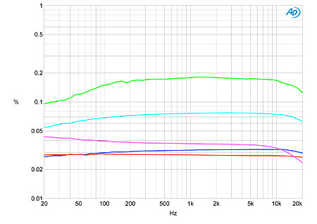
Fig.5 Aesthetix Atlas, THD+N (%) vs frequency at 10V into: 8 ohms (left channel blue, right red), 4 ohms (left cyan, right magenta), 2 ohms (green).
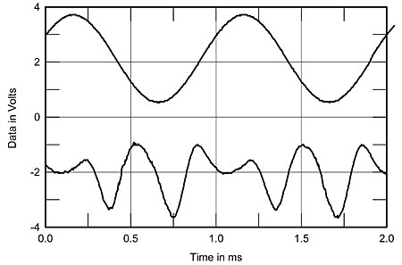
Fig.6 Aesthetix Atlas, 1kHz waveform at 14.3W into 4 ohms (top), 0.025% THD+N; distortion and noise waveform with fundamental notched out (bottom, not to scale).
The distortion waveform at a moderate power level primarily consists of the second and third harmonics (fig.6). At higher levels, a regular series of harmonics makes an appearance (fig.7), though even the highest-level, higher-order components, the seventh and ninth, lie at –86dB (0.006%), which will be below audibility. At low powers, the only harmonics that can be seen above the noise floor are the second and third (fig.8), though the third is higher in the left channel (blue) than in the right (red). The left channel is also noisier, as expected from the earlier tests, with a sideband pair at ±120Hz surrounding the peak at 1kHz; this behavior is power-supply related. The actual 120Hz component, however, lies at a respectable –100dB in the left channel (0.001%) and –104dB (0.0006%) in the right.
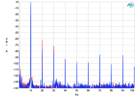
Fig.7 Aesthetix Atlas, spectrum of 1kHz sinewave, DC–10kHz, at 104W into 8 ohms (left channel blue, right red; linear frequency scale).
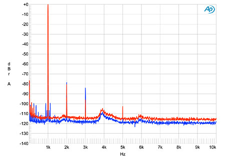
Fig.8 Aesthetix Atlas, spectrum of 1kHz sinewave, DC–10kHz, at 1W into 8 ohms (left channel blue, right red; linear frequency scale).
Finally, with its reduced linearity at high powers, the Atlas gave good rather than great results with the high-power intermodulation test. At a level around 3dB below visible waveform clipping into 4 ohms (fig.9), the 1kHz difference component was the highest in level, at –96dB (0.007%) in the left channel but –66dB (0.05%) in the right. The higher-order intermodulation products at 18 and 21kHz are better matched between the two channels, however, at –77 and –74dB, left and right channels, respectively.
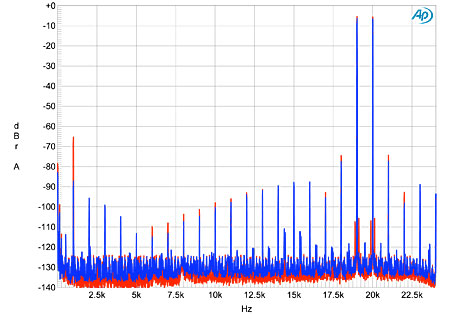
Fig.9 Aesthetix Atlas, HF intermodulation spectrum, DC–24kHz, 19+20kHz at 210W peak into 4 ohms (linear frequency scale).
The Aesthetix Atlas is a powerful amplifier, and other than some differences between the two channels that may well be due to problems with an input tube, its measured behavior mainly relates to the designer's decision not to use overall loop negative feedback.—John Atkinson
- Log in or register to post comments


