Sidebar 3: Measurements
I used my Audio Precision SYS2722 system to measure the Vitus RI-101 Mk.II, repeating some tests with the magazine's Audio Precision APx555. I connected the amplifier's Line 1 balanced inputs to the Audio Precision's balanced outputs and immediately discovered that one channel's output had been damaged during shipping. US distributor Aldo Filippelli therefore arranged for a second sample to be shipped to me from Manhattan retailer Park Avenue Audio. Jason's sample had the serial number US-D0017; that of the new sample was US-D0005.
Both channels of this sample matched closely, so I proceeded with the measurements. I preconditioned the new RI-101 before the measurements by following the CEA's recommendation of running it at one-eighth that power into 8 ohms for 30 minutes. Following that period, the top panel was warm, at 100.7°F (38.2°C), and the internal heatsinks were hot, at 139.3°F (59.6°C).
The RI-101 preserved absolute polarity with both its balanced and unbalanced line inputs at both the speaker and preamplifier outputs. The volume control operated in accurate 1dB steps and with the volume control set to the maximum, "+8.0dB," the voltage gain at 1kHz was 36dB, balanced, and 35.4dB, unbalanced, into 8 ohms from the loudspeaker outputs, 0.4dB from the preamplifier outputs. The line input impedance is specified as 16k ohms for both input types. I measured 30k ohms at 20Hz and 1kHz and 14k ohms at 20kHz for the single-ended inputs, 33k ohms across the audioband for the balanced inputs.
The behavior of the new amplifier's Ethernet input was very similar to that of the original sample. It preserved absolute polarity from all the outputs. With the volume control set to "0.0dB," the RI-101's voltage into 8 ohms at the speaker outputs with a 1kHz tone at –20dBFS was 4.4V, which means that a tone at 0dBFS will be reproduced just 1dB below the clipping voltage into that load. The level with that tone was 230mV at the preamplifier output; I continued the digital input testing from that output with the volume control set to "0.0dB."
Although the new sample of the Vitus RI-101 Mk.II had both loudspeaker outputs working correctly and offered slightly lower noise and distortion than the original sample, it still didn't perform as well as I expected on the test bench, either from its line-level analog inputs or from its Streamer digital input. The latter, in particular, has lower resolution than I usually find from a DAC that uses the ESS Sabre ES9038Pro chip.—John Atkinson
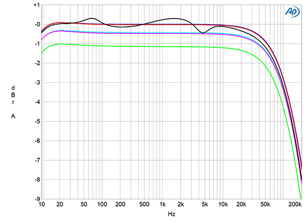
Fig.1 Vitus RI-101 Mk.II, balanced line input, frequency response at 2.83V into: simulated loudspeaker load (gray), 8 ohms (left channel blue, right red), 4 ohms (left cyan, right magenta), 2 ohms (green) (1dB/vertical div.).
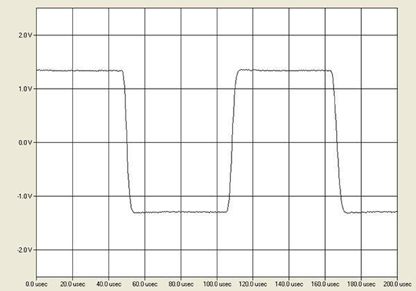
Fig.2 Vitus RI-101 Mk.II, line input, small-signal 10kHz squarewave into 8 ohms.
The balanced preamplifier output impedance was a usefully low 66 ohms from 20Hz to 20kHz. The loudspeaker output impedance, including 6' of spaced-pair speaker cable, was slightly lower than that of the original amplifier, at 0.47 ohms in the bass and midrange and 0.49 ohm at the top of the audioband. Consequently, the modulation of the RI-101's frequency response due to the Ohm's law interaction between this impedance and the impedance of our standard simulated loudspeaker was ±0.4dB (fig.1, gray trace). The amplifier's response into resistive loads was flat in the audioband, with its output into 8 ohms (blue and red traces) down by 3dB at 100kHz. This graph was taken with the volume control set to "0.0dB"; the close channel matching was preserved at all volume control settings. The RI-101's reproduction of a 10kHz squarewave (fig.2) had short risetimes, with no overshoot or ringing.
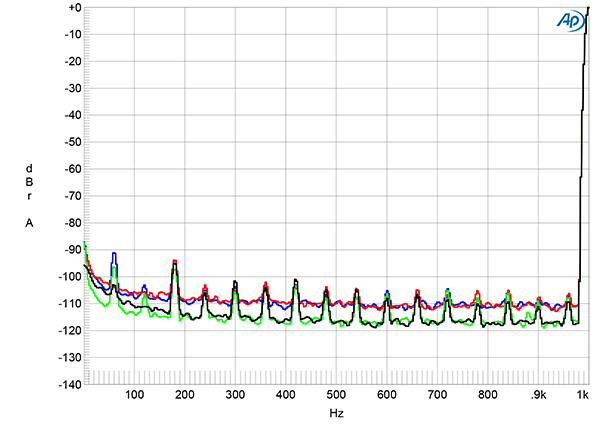
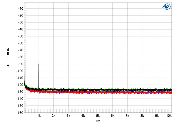
Fig.3 Vitus RI-101 Mk.II, line input, spectrum of 1kHz sinewave, DC–1kHz, at 1Wpc into 8 ohms with volume control set to "+8.0dB" (left channel blue, right red), and to "–12.0dB" (left channel green, right gray) (linear frequency scale).
Channel separation was superb, at >100dB in both directions below 10kHz. The wideband, unweighted signal/noise ratio, taken with the unbalanced input shorted to ground and the volume control set to "0.0dB," was a good 69.4dB in both channels ref. 2.83V, which is equivalent to 1W into 8 ohms. This ratio improved to 81.3dB when the measurement bandwidth was restricted to the audioband, and to 84.2dB when A-weighted. The spectrum of the noisefloor at 1W into 8 ohms with the volume control set to the maximum is shown as the blue and red traces in fig.3. The level of random noise dropped by 6dB with the volume control setting reduced by 20dB and the input signal increased by the same 20dB, but the levels of the supply-related spuriae at 60Hz and its odd-order harmonics were identical, at –90dB ref. 2.83V and below.
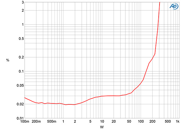
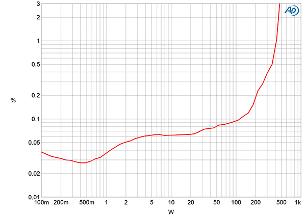
Fig.4 Vitus RI-101 Mk.II, distortion (%) vs 1kHz continuous output power into 8 ohms.
Fig.5 Vitus RI-101 Mk.II, distortion (%) vs 1kHz continuous output power into 4 ohms.
Stereophile specifies an amplifier's clipping power as when the THD+noise reaches 1%. With both channels driven and the volume control set to "0.0dB," the clipping power into 8 ohms was slightly lower than the specification, at 290W into 8 ohms (24.62dBW, fig.4). This is 0.11dB lower than the specified 300W into this load (24.73dBW). The RI-101 did reach its specified output power at 3% THD+N. The amplifier's maximum power into 4 ohms, specified as 600W, was 410W (23.12dBW, fig.5) at 1% THD+N and 470W (23.71dBW) at 3% THD+N. The wall voltage had dropped from 118.4V with the amplifier idling to 116.4V at the clipping power into this load. Vitus doesn't specify the RI-101's maximum power into 2 ohms, but the amplifier clipped at 360W (19.54dBW) into this load, the wall voltage dropping to 115.4V.
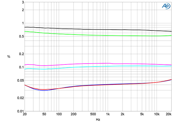
Fig.6 Vitus RI-101 Mk.II, THD+N (%) vs frequency at 20V into: 8 ohms (left channel blue, right red), 4 ohms (left channel cyan, right magenta), and 2 ohms (left channel green, right gray).
Fig.6 shows how the THD+N percentage varied with frequency at 20V, which is equivalent to 50W into 8 ohms, 100W into 4 ohms, and 200W into 2 ohms. The THD+N was respectably low into 8 ohms (blue and red traces) but increased into the lower impedances, exceeding 0.5% into 2 ohms (green and gray traces). However, there was no increase in the THD+N percentage at high frequencies, which suggests that the amplifier has a respectably wide open-loop bandwidth.
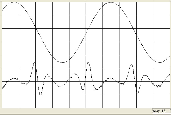
Fig.7 Vitus RI-101 Mk.II, 1kHz waveform at 50W into 8 ohms, 0.032% THD+N (top); distortion and noise waveform with fundamental notched out (bottom, not to scale).
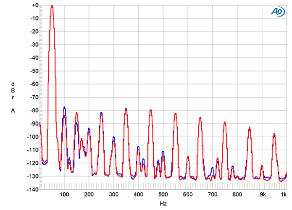
Fig.8 Vitus RI-101 Mk.II, spectrum of 50Hz sinewave, DC–1kHz, at 50W into 8 ohms (left channel blue, right red; linear frequency scale).
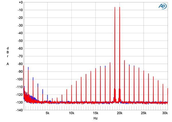
Fig.9 Vitus RI-101 Mk.II, HF intermodulation spectrum, DC–30kHz, 19+20kHz at 50W peak into 8 ohms (left channel blue, right red; linear frequency scale).
Vitus says that the amplifier's output stage transitions from class-A to class-AB at approximately 8W into 8 ohms. I wasn't surprised to find, therefore, that the THD+N waveform at 50W into 8 ohms had spikes present at the waveform's zero-crossing points (fig.7). These crossover spikes correlate with the presence of high-order harmonics in the output (fig.8), though these all lie at or below –80dB (0.01%). The high-order intermodulation products with an equal mix of 19 and 20kHz tones at the same peak power all lie at or below –80dB (fig.9), with the second-order difference product at 1kHz 4dB lower in level.
I had examined the performance of the original Vitus RI-101's optional AES3 and S/PDIF digital inputs with data sourced from the SYS2722, repeating some tests with the Streamer Ethernet input. However, while the new sample's AES3 and S/PDIF inputs locked to datastreams with sample rates up to 192kHz, the levels at both the loudspeaker and preamplifier outputs changed unpredictably, with occasional random noise. It is possible, therefore, that this board was not functioning correctly, so I continued the testing with network data fed to the Streamer input from Roon.
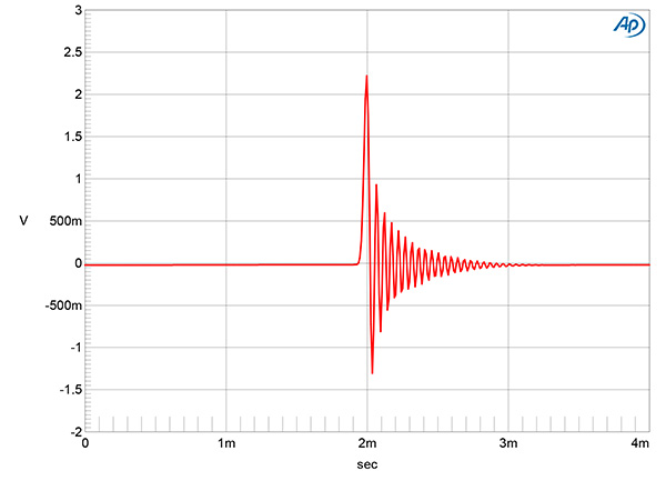
Fig.10 Vitus RI-101 Mk.II, network data, impulse response (one sample at 0dBFS, 44.1kHz sampling, 4ms time window).
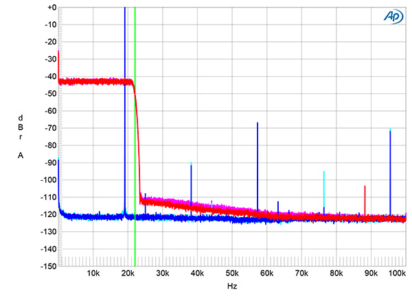
Fig.11 Vitus RI-101 Mk.II, network data, wideband spectrum of white noise at –4dBFS (left channel red, right magenta) and 19.1kHz tone at 0dBFS (left blue, right cyan) into 100k ohms with data sampled at 44.1kHz (20dB/vertical div.).
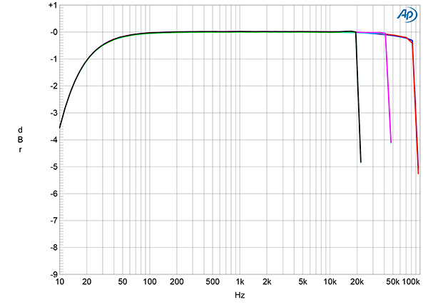
Fig.12 Vitus RI-101 Mk.II, network data, frequency response at –12dBFS into 100k ohms with data sampled at: 44.1kHz (left channel green, right gray), 96kHz (left cyan, right magenta), and 192kHz (left blue, right red) (1dB/vertical div.).
Fig.10 shows the RI-101's impulse response with 44.1kHz data. The filter is a minimum-phase type, with all the ringing following the single sample at 0dBFS. The magenta and red traces in fig.12 show the reconstruction filter's ultrasonic rolloff with data sampled at 44.1kHz. They reach full stop-band attenuation at just above half the sample rate (this indicated by the vertical green line), with the aliased image at 25kHz of a full-scale tone at 19.1kHz (cyan, blue) suppressed by 107dB. The third harmonic of the 19.1kHz tone lay close to –70dB (0.06%). The frequency response with 44.1kHz, 96kHz, and 192kHz data is flat almost to half of each sample rate then rolls off sharply (fig.12). The low-frequency rolloff in this graph, which reaches –3dB at 12Hz, was characteristic of the preamplifier outputs.
Fig.13 Vitus RI-101 Mk.II, network data, spectrum with noise and spuriae of dithered 1kHz tone at –90dBFS with: 16-bit data (left channel green, right gray), 24-bit data (left blue, right red) (20dB/vertical div.).
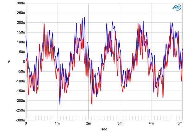
Fig.14 Vitus RI-101 Mk.II, network data, waveform of undithered 1kHz sinewave at –90.31dBFS, 16-bit data (left channel blue, right red).
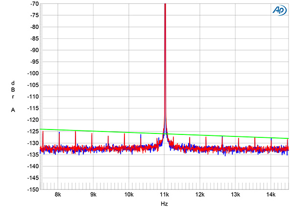
Fig.15 Vitus RI-101 Mk.II, network data, high-resolution jitter spectrum of analog output signal, 11.025kHz at –6dBFS, sampled at 44.1kHz with LSB toggled at 229Hz: 16-bit data (left channel blue, right red). Center frequency of trace, 11.025kHz; frequency range, ±3.5kHz.
An increase in bit depth from 16 to 24, with dithered data representing a 1kHz tone at –90dBFS, dropped the RI-101's noisefloor by 5dB (fig.13). This implies a resolution of about 17 bits. When I played undithered data representing a tone at exactly –90.31dBFS, the waveform's three DC voltage levels described by the data were obscured by noise (fig.14). This random noise can also be seen in the spectrum of the RI-101's output when it was fed high-level 16-bit J-Test network data (fig.15). The odd-order harmonics of the undithered low-frequency LSB-level squarewave lie close to the correct levels.


