Sidebar 3: Measurements
With the Aurender Flow's battery fully charged, I measured it with my Audio Precision SYS2722 system (see www.ap.com and the January 2008 "As We See It"). Sources were TosLink from the SYS2722, USB from my 2012 MacBook Pro (running on battery power), or USB from my iPad 2 via the camera connection kit. Macintosh's USB Prober utility reported the Flow's product string as "Aurender-FLOW-6027 Output" and the manufacturer string as "XMOS." USB Prober also confirmed that the Flow's USB port operated in the optimal isochronous asynchronous mode. The TosLink input locked to datastreams with sample rates up to 96kHz, the USB input up to 384kHz. The iPad was restricted to sample rates of 96kHz and below.
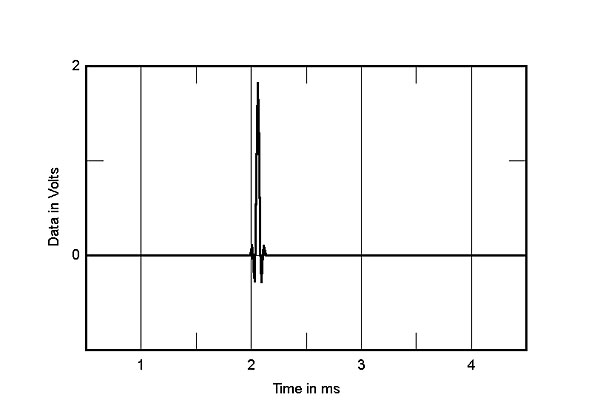
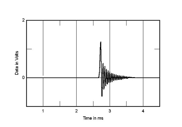
The maximum output level at 1kHz was 5.19V or 2.07V for both the fixed output setting and the variable output with the volume control set to "0.0dB." (The output level was set to 5V for all testing.) The volume control operated in accurate 0.5dB steps. The output preserved absolute polarity and the output impedance was very low, at 0.4 ohm across the audioband (including 6' of cable). The impulse response with 44.1kHz data depended on the reconstruction filter in use. The default, pcm0, is a conventional FIR type with a time-symmetrical impulse response (fig.1), while pcm1 (fig.2) is a short type that, as the Flow's manual states, "virtually eliminates ringing from signals." However, the manual also states that this is a "minimum phase" filter, which the impulse response shows not to be correct (footnote 1). However, pcm2 is indeed a minimum-phase type, as revealed by its impulse response (fig.3), where all the ringing occurs after the initial transient.

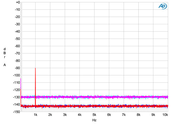
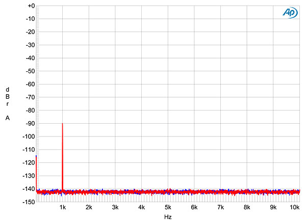
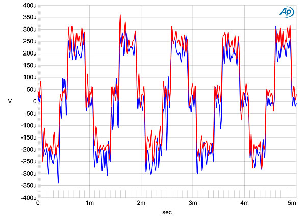
 The drop in the noise floor of >12dB in fig.9 when the bit depth is increased from 16 to 24 suggests that the Flow has at least 18-bit resolution, which is excellent. This graph was taken with S/PDIF data; I obtained identical results with both USB and iOS sources. (An iPad will indeed output 24-bit data via the camera connection kit, fig.10.) The Aurender's reproduction of an undithered 16-bit signal at exactly –90.31dBFS was excellent (fig.11), with the three DC voltage levels clearly and symmetrically resolved. With a 24-bit representation of the same signal, the Flow output a nice sinewave (fig.12).
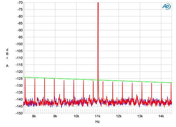
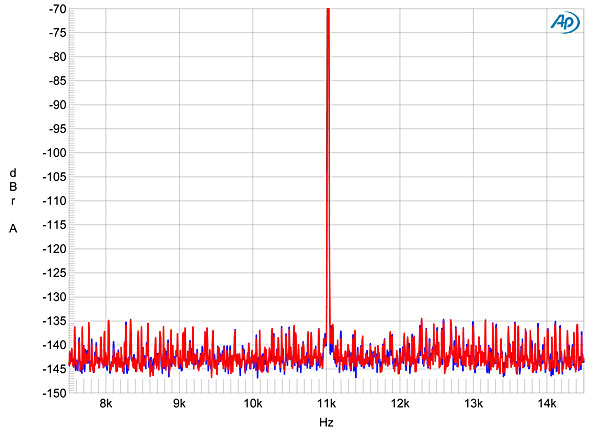
 All three sources—S/PDIF, USB, iOS—gave identical results when it came to rejection of jitter. Fig.16 is a narrowband spectral analysis of the Flow's analog output when fed 16-bit/44.1kHz S/PDIF data representing the Miller-Dunn J-Test signal. All the odd-order harmonics of the LSB-level low-frequency squarewave are very close to their correct levels (green line), and there are virtually no sidebands around the high-level 11.025kHz tone. There were no sidebands with 24-bit data (fig.17), though the noise floor looked more ragged than is usually the case with state-of-the-art digital processors.
 Overall, the Aurender Flow offers superb measured performance.—John Atkinson
Footnote 1: Aurender has since updated the manual and website to correctly describe the nature of the filters. Footnote 2: This test was suggested to me by Jürgen Reis, chief engineer of MBL.
Fig.1 Aurender Flow, pcm0 filter, impulse response at 44.1kHz (4ms time window).
Fig.2 Aurender Flow, pcm1 filter, impulse response at 44.1kHz (4ms time window).
Fig.3 Aurender Flow, pcm2 filter impulse response at 44.1kHz (4ms time window).
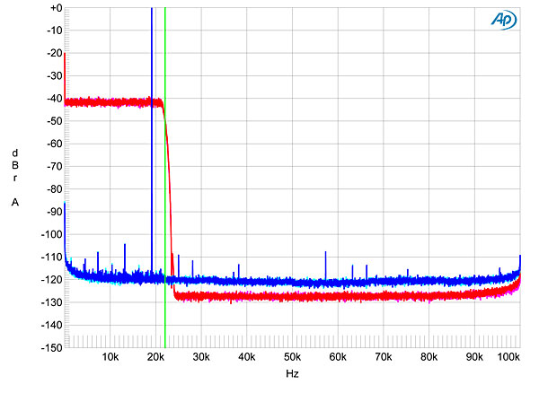
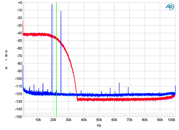
Although pcm2 is described in the manual as "a slow roll-off PCM filter" by means of which the output signal "will be slightly attenuated," the red and magenta traces in fig.4 indicate that this is not the case, the 44.1kHz-sampled white noise rolling off sharply above 22.05kHz (green vertical line) to reach the stopband noise floor by 24kHz (footnote 2). It is the pcm1 filter that offers the slow and early rolloff (fig.5), correlating with the short filter length, and allowing the image of the full-scale tone at 19.1kHz in the graph (blue and cyan traces) to lie just 10dB below the level of the fundamental tone. But note the very low levels of the distortion harmonics in figs.4 and 5.
Fig.4 Aurender Flow, pcm2 filter, wideband spectrum of white noise at –4dBFS (left channel red, right magenta) and 19.1kHz tone at 0dBFS (left blue, right cyan), with data sampled at 44.1kHz (20dB/vertical div.).
Fig.5 Aurender Flow, pcm1 filter, wideband spectrum of white noise at –4dBFS (left channel red, right magenta) and 19.1kHz tone at 0dBFS (left blue, right cyan), with data sampled at 44.1kHz (20dB/vertical div.).
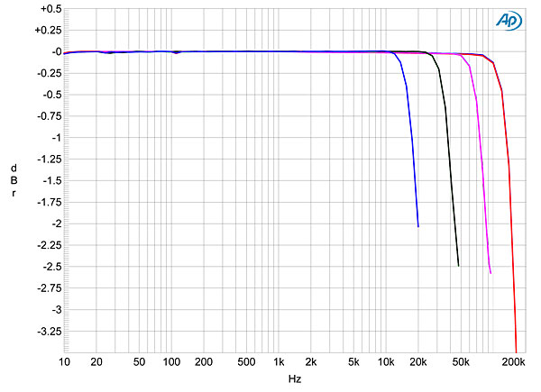
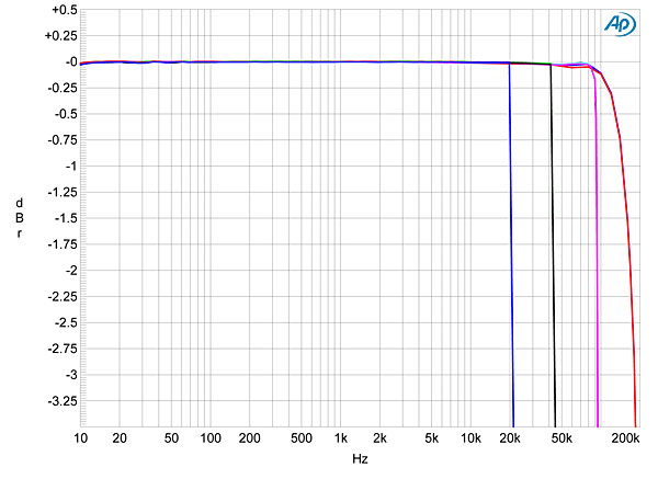
This early rolloff with pcm1 can be seen in fig.6, which plots the Flow's frequency response at sample rates of 44.1, 96, 192, and 384kHz. With the lowest sample rate, the signal is down by 2dB at 20kHz. Filters pcm0 and pcm2 behaved identically, offering flat response almost up to the Nyquist frequency for the lower sample rates, but an earlier, slower rolloff for data sampled at 384kHz (fig.7 red trace). Channel separation (not shown) was superb, at >120dB below 3kHz, while the Aurender's noise floor was free from idle tones and other spuriae (fig.8).
Fig.6 Aurender Flow, pcm1 filter, frequency response at –12dBFS into 100k ohms with data sampled at: 44.1kHz (left channel blue, right red), 96kHz (left green, right gray), 192kHz (left cyan, right magenta), 384kHz (left blue, right red) (0.5dB/vertical div.).
Fig.7 Aurender Flow, pcm0 filter, frequency response at –12dBFS into 100k ohms with data sampled at: 44.1kHz (left channel blue, right red), 96kHz (left green, right gray), 192kHz (left cyan, right magenta), 384kHz (left blue, right red) (0.5dB/vertical div.).
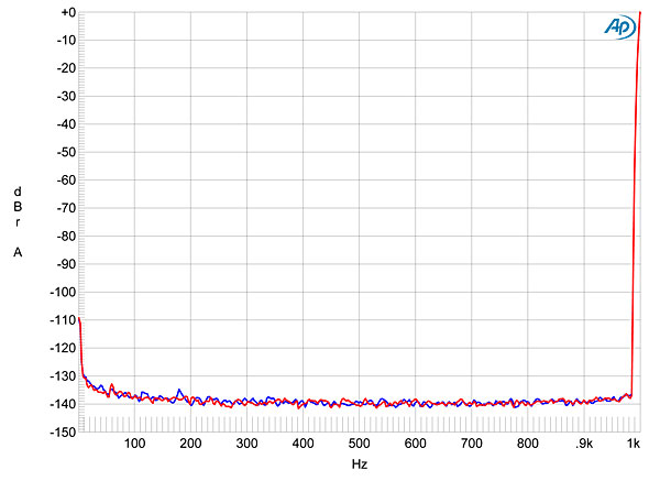
Fig.8 Aurender Flow, spectrum of 1kHz sinewave, DC–1kHz, at 0dBFS into 100k ohms (left channel blue, right red; linear frequency scale).
Fig.9 Aurender Flow, spectrum with noise and spuriae of dithered 1kHz tone at –90dBFS with: 16-bit data (left channel cyan, right magenta), 24-bit data (left blue, right red) (20dB/vertical div.).
Fig.10 Aurender Flow, spectrum with noise and spuriae of dithered 1kHz tone at –90dBFS with 24-bit iPad data (left blue, right red) (20dB/vertical div.).
Fig.11 Aurender Flow, waveform of undithered 1kHz sinewave at –90.31dBFS, 16-bit data (left channel blue, right red).
Fig.12 Aurender Flow, waveform of undithered 1kHz sinewave at –90.31dBFS, 24-bit data (left channel blue, right red).
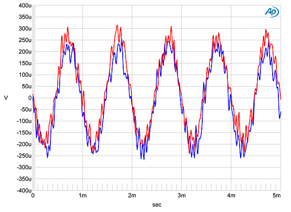
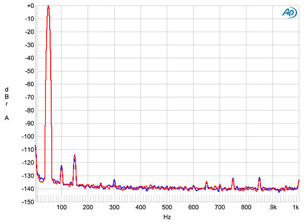
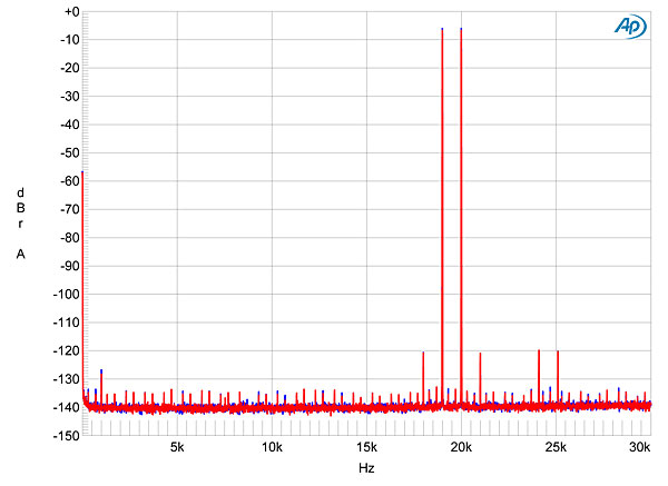
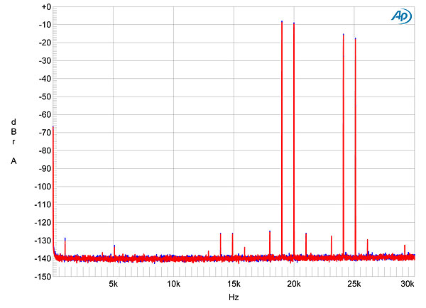
As hinted in figs. 3 and 4, the Flow is superbly linear, a full-scale 50Hz tone into 300 ohms (fig.13) giving rise to third-harmonic distortion at –114dB (0.0002%) and an even lower level of second harmonic. With an equal mix of 19 and 20kHz tones, the sum peaking at 0dBFS, filters pcm0 and pcm2 gave a negligible amount of intermodulation distortion (fig.14), although, as expected, the slow rolloff of pcm1 gave rise to high-level ultrasonic images of the two fundamental tones (fig.15). But actual intermodulation distortion is still extremely low with this filter.
Fig.13 Aurender Flow, spectrum of 50Hz sinewave, DC–1kHz, at 0dBFS into 300 ohms (left channel blue, right red; linear frequency scale).
Fig.14 Aurender Flow, pcm2 filter, HF intermodulation spectrum, DC–30kHz, 19+20kHz at 0dBFS into 300 ohms, 44.1kHz data (left channel blue, right red; linear frequency scale).
Fig.15 Aurender Flow, pcm1 filter, HF intermodulation spectrum, DC–30kHz, 19+20kHz at 0dBFS into 300 ohms, 44.1kHz data (left channel blue, right red; linear frequency scale).
Fig.16 Aurender Flow, high-resolution jitter spectrum of analog output signal, 11.025kHz at –6dBFS, sampled at 44.1kHz with LSB toggled at 229Hz: 16-bit data via S/PDIF (left channel blue, right red). Center frequency of trace, 11.025kHz; frequency range, ±3.5kHz.
Fig.17 Aurender Flow, high-resolution jitter spectrum of analog output signal, 11.025kHz at –6dBFS, sampled at 44.1kHz with LSB toggled at 229Hz: 24-bit data via S/PDIF (left channel blue, right red). Center frequency of trace, 11.025kHz; frequency range, ±3.5kHz.
Footnote 1: Aurender has since updated the manual and website to correctly describe the nature of the filters. Footnote 2: This test was suggested to me by Jürgen Reis, chief engineer of MBL.