Sidebar 3: Measurements
I used DRA Labs' MLSSA system, a calibrated DPA 4006 microphone, and an Earthworks microphone preamplifier to measure the quasi-anechoic frequency- and time-domain behavior of one of the Audiovector R 3 Arretés—serial number 202084—in the farfield. I used an Earthworks QTC-40 microphone, which has a ¼" capsule, for the nearfield responses, examined the loudspeaker's impedance with Dayton Audio's DATS V2 system, and investigated the enclosure's resonant modes with a plastic-tape accelerometer.
Audiovector specifies the sensitivity of the R 3 Arreté as 90.5dB/W/m. My B-weighted estimate of the R 3 Arreté's voltage sensitivity was lower than that, at 87.2dB(B)/2.83V/m. A possible reason for this discrepancy is examined later in this report.
Footnote 1: EPDR is the resistive load that gives rise to the same peak dissipation in an amplifier's output devices as the loudspeaker. See "Audio Power Amplifiers for Loudspeaker Loads," JAES, Vol.42 No.9, September 1994, and stereophile.com/reference/707heavy/index.html. Footnote 2: According to Audiovector's Mads Kliforth, the Arreté tweeter's "S-stop filter (gold mesh) . . . controls sibilance and at the same time it works like an 'integrator,' so the cooperation with the midrange below improves."
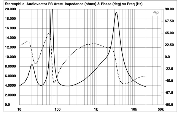
Fig.1 Audiovector R 3 Arreté, electrical impedance (solid) and phase (dashed) (2 ohms/vertical div.).
The Audiovector R 3 Arreté's nominal impedance is specified as 8 ohms. The impedance magnitude (fig.1, solid trace) remains above 6 ohms from the upper midrange through the mid-treble region, with a minimum value of 3.925 ohms at 190Hz. The electrical phase angle (fig.1, dotted trace) is occasionally high, which means that the effective resistance, or EPDR (footnote 1), drops below 3 ohms over most of the audioband. The minimum EPDR values are 2.03 ohms at 47Hz, 1.96 ohms at 101Hz, 2.58 ohms at 430Hz, and 1.4 ohms at 20kHz. Other than the last value, recorded music can have high energy at the frequencies of these minima. The R 3 Arreté is a demanding load for the partnering amplifier.
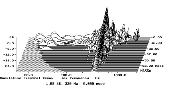
Fig.2 Audiovector R 3 Arreté, cumulative spectral-decay plot calculated from output of accelerometer fastened to sidewall level with the upper woofer (MLS driving voltage to speaker, 7.55V; measurement bandwidth, 2kHz).
There is a very slight wrinkle just above 300Hz in the impedance traces in fig.1, which might be due to a resonant mode of some kind. Most of the enclosure's panels seemed relatively inert when I rapped them with my knuckles, but I found a strong resonance at 320Hz on the sidewalls level with the upper woofer (fig.2). The affected area of the sidewall was relatively small, and the mode has a high Q (Quality Factor), both of which will work against there being audible consequences. However, 320Hz is close to the frequency of the note E above Middle C in the well-tempered scale, so this mode may well be excited a lot of the time.
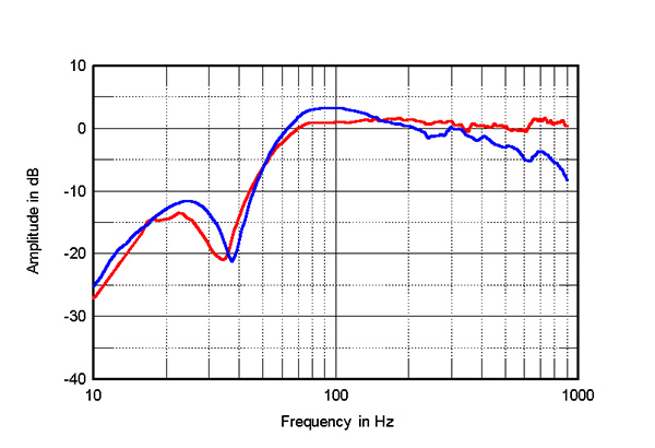
Fig.3 Audiovector R 3 Arreté, nearfield responses of the lower woofer (blue) and the upper woofer (red).
Audiovector describes the R 3 Arreté as a "2.5-way" design, which means that while the speaker has two woofers, only one extends sufficiently high in frequency to cross over to the tweeter. This can be seen in fig.3, which shows the responses of the lower woofer (blue trace) and the upper woofer (red trace), measured in the nearfield. The lower woofer slowly rolls off above 300Hz, while the upper woofer's output is flat to the 900Hz limit of these measurements. The blue trace has the usual rise in the upper bass, which will be due to the nearfield measurement technique. This suggests that the lower woofer's reflex alignment is what is called maximally flat, which optimizes low-frequency extension and control. There is no upper-bass boost in the red trace, which implies that the upper woofer's alignment is overdamped. Note that the minimum-motion notch in the woofers' outputs, which is when the cones are held stationary by the back pressure from the port resonance, lies at slightly different frequencies between 30Hz and 40Hz.
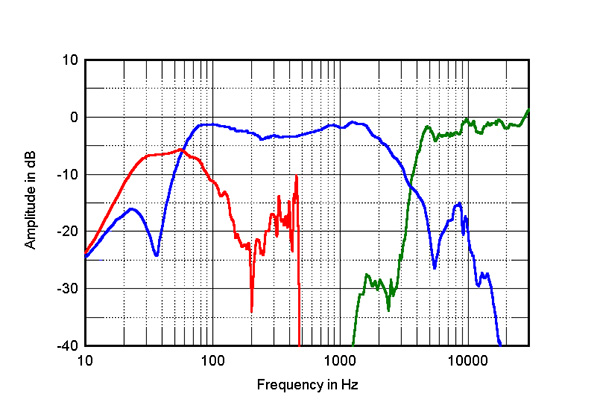
Fig.4 Audiovector R 3 Arreté, acoustic crossover on tweeter axis at 50", corrected for microphone response, with the summed nearfield responses of the woofers (blue) and the downward-firing port (red), respectively plotted below 350Hz and 500Hz.
The sum of the two woofers' nearfield responses is shown as the blue trace in fig.4. The combined minimum-motion notch lies at 36Hz, and the response of the downward-firing port, again measured in the nearfield (red trace), peaks broadly between 22Hz and 90Hz. The port's output will be reinforced by its proximity to the floor, which means that the R 3 Arreté will offer extended low frequencies in-room. Audiovector refers to the twin ports at the top of the rear panel as the "Soundstage Enhancement Concept." These ports allow the tweeter's backwave to be radiated into the room. I found the nearfield output from these ports to be very low in level, averaging around 24dB below the nearfield, forward-firing output of the tweeter.
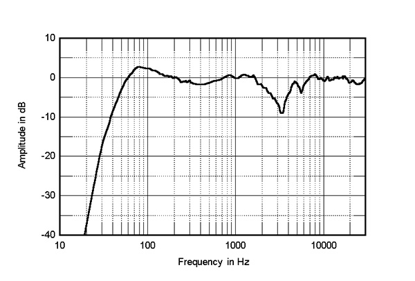
Fig.5 Audiovector R 3 Arreté, anechoic response on tweeter axis at 50", averaged across 30° horizontal window and corrected for microphone response, with the complex sum of the nearfield woofer and port responses plotted below 310Hz.
According to the specifications, the crossover frequency between the upper woofer and tweeter is set at 2.9kHz. However, it appears from fig.4 that the woofers' farfield output (blue trace above 350Hz) doesn't extend sufficiently high in frequency and the tweeter's farfield output (green trace) doesn't extend sufficiently low in frequency to allow a flat frequency response in the crossover region. This gives rise to an 8dB suckout centered on 3.3kHz in the R 3 Arreté's quasi-anechoic farfield response on the tweeter axis (black trace above 310Hz in fig.5), which is otherwise impressively even. (This lack of presence-region energy will be the reason for the shortfall in my estimated sensitivity. I did try connecting the "Freedom Grounding Concept" binding post, but this didn't affect the measured sensitivity or response.)
I initially thought that this suckout might be due to one of the drive units being connected in the incorrect polarity, leading to destructive interference in the crossover region. However, the response with the tweeter connected in inverted polarity was identical to that with it correctly connected.
If this behavior affected only the sample I measured and not the other sample JCA auditioned, the stereo image with a dual-mono signal would pull to one side in the low treble. (It wasn't possible for me to measure both samples.) However, when I asked JCA about this, he replied that, listening to correlated pink noise, he hadn't noticed any imbalance. This suggests that both samples were behaving identically. Audiovector uses what they call an "S-stop filter" to reduce sibilance, so perhaps the suckout in the presence region is due to the action of that filter (footnote 2).
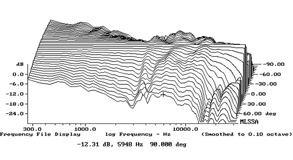
Fig.6 Audiovector R 3 Arreté, lateral response family at 50", normalized to response on tweeter axis, from back to front: differences in response 90–5° off axis, reference response, differences in response 5–90° off axis.
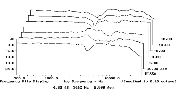
Fig.7 Audiovector R 3 Arreté, vertical response family at 50", normalized to response on tweeter axis, from back to front: differences in response 15–5° above axis, reference response, differences in response 5–15° below axis.
The Audiovector's horizontal radiation pattern, normalized to the response on the tweeter axis, which therefore appears as a straight line, is shown in fig.6. The on-axis suckout deepens to the speaker's sides, though the dispersion in the region covered by the AMT tweeter is wide up to 15kHz or so. Fig.7 shows the R 3 Arreté's dispersion in the vertical plane, again normalized to the response on the tweeter axis, which is 38" from the floor, indicating that the suckout tends to fill in slightly 15° above the tweeter axis and 5°–10° below, though the latter will be an impractically low ear height.
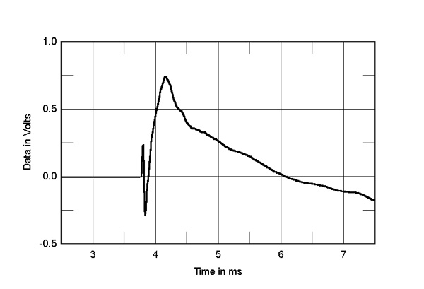
Fig.8 Audiovector R 3 Arreté, step response on tweeter axis at 50" (5ms time window, 30kHz bandwidth).
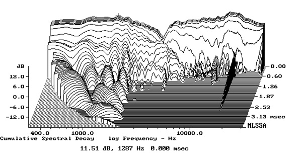
Fig.9 Audiovector R 3 Arreté, cumulative spectral-decay plot on tweeter axis at 50" (0.15ms risetime).
In the time domain, the R 3 Arreté's step response (fig.8) indicates that all three drive units are connected in positive acoustic polarity. The output of the tweeter arrives first at the microphone, followed by that of the two woofers. The Audiovector's cumulative spectral-decay (waterfall) plot (fig.9) is very clean, especially in the region covered by the tweeter.
Putting to one side that current-hungry impedance, if it wasn't for that presence-region suckout the Audiovector R 3 Arreté would offer excellent measured performance, with an otherwise even balance, extended low frequencies in-room, and a clean spectral decay. With the suckout, however, I would expect this loudspeaker's treble to sound polite or laid back.—John Atkinson
Footnote 1: EPDR is the resistive load that gives rise to the same peak dissipation in an amplifier's output devices as the loudspeaker. See "Audio Power Amplifiers for Loudspeaker Loads," JAES, Vol.42 No.9, September 1994, and stereophile.com/reference/707heavy/index.html. Footnote 2: According to Audiovector's Mads Kliforth, the Arreté tweeter's "S-stop filter (gold mesh) . . . controls sibilance and at the same time it works like an 'integrator,' so the cooperation with the midrange below improves."