Sidebar 3: Measurements
The review sample of the Reference phono preamplifier came to my lab via the manufacturer, where they resolved what had been the cause of the occasional noise problem noted by Michael. I reinstalled the tubes and let it break in for about four hours before I did any measurements.
Voltage gain was slightly higher than specified, at 50.9dB (Low Gain inputs) and 71dB (High Gain). Both are relatively high figures, implying good compatibility with low-output moving-coil cartridges. Depending on the overload margin, however, there might be some problems with very "hot" moving-magnet models. The input impedance was also slightly higher than specified, at 48.5k ohms and 290 ohms, respectively, but the differences are negligible. The output impedance was to spec at a low 201 ohms. The Reference didn't invert signal polarity via either input.
Via the Low Gain inputs (fig.1, top traces), the RIAA error was superbly low. However, via the High Gain inputs (fig.1, bottom traces), a slight low-frequency rolloff (-0.5dB at 20Hz) can be seen, as well as a more severe high-frequency one (-3dB at 11kHz). I suspect that this was due to interaction between the Reference's transformer inputs and the Audio Precision System One with its 25 ohm source impedance. (Typical low-output MCs have a source impedance around one tenth of that figure.) To check, I looked at the Reference's spectral balance in my own system using my Linn Arkiv cartridge, the pink noise from the Denon Test LP, and an Audio Control SA-3050A 1/3-octave analyzer. The result was as flat as that shown in fig.1 from the Low Gain inputs.
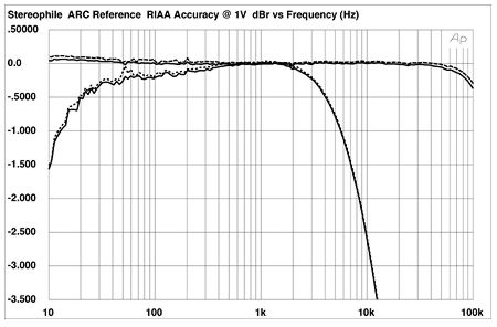 Fig.1 Audio Research Reference, RIAA error into 100k ohms at 5mV/1kHz input, Low Gain (top), and High Gain (bottom), driven by Audio Precision System One with 25 ohms source impedance. (Right channel dashed, 0.5dB/vertical div.)
I had some problems measuring both the preamplifier's noise levels and the crosstalk. Physically tying the inputs to ground with an RCA shorting plug gave superbly low noise levels, and channel separation that remained above 80dB over most of the audio band. Fig.2, for example, shows a spectral analysis of the Low Gain inputs' noise floors referenced to 5mV at 1kHz, this equivalent to a signal/noise ratio of 87dB measured over a wide (10Hz-500kHz) bandwidth. However, instead of shorting RCA plugs, I connected the Audio Precision's grounded outputs to the preamplifier with 6' of shielded Canare cable. Though this is theoretically identical in electrical terms, peaks in the noise now appeared at 16kHz and 32kHz. It turned out that the Reference was picking up this noise from a TV that had been left switched on, but without an input signal in the Stereophile lab. These were visible as HF hash on the oscilloscope display. I suspect that the Reference is susceptible to picking up stray RFI on its inputs. This means that while some cartridge and interconnect combinations might work well, others will be more problematic.
Fig.1 Audio Research Reference, RIAA error into 100k ohms at 5mV/1kHz input, Low Gain (top), and High Gain (bottom), driven by Audio Precision System One with 25 ohms source impedance. (Right channel dashed, 0.5dB/vertical div.)
I had some problems measuring both the preamplifier's noise levels and the crosstalk. Physically tying the inputs to ground with an RCA shorting plug gave superbly low noise levels, and channel separation that remained above 80dB over most of the audio band. Fig.2, for example, shows a spectral analysis of the Low Gain inputs' noise floors referenced to 5mV at 1kHz, this equivalent to a signal/noise ratio of 87dB measured over a wide (10Hz-500kHz) bandwidth. However, instead of shorting RCA plugs, I connected the Audio Precision's grounded outputs to the preamplifier with 6' of shielded Canare cable. Though this is theoretically identical in electrical terms, peaks in the noise now appeared at 16kHz and 32kHz. It turned out that the Reference was picking up this noise from a TV that had been left switched on, but without an input signal in the Stereophile lab. These were visible as HF hash on the oscilloscope display. I suspect that the Reference is susceptible to picking up stray RFI on its inputs. This means that while some cartridge and interconnect combinations might work well, others will be more problematic.
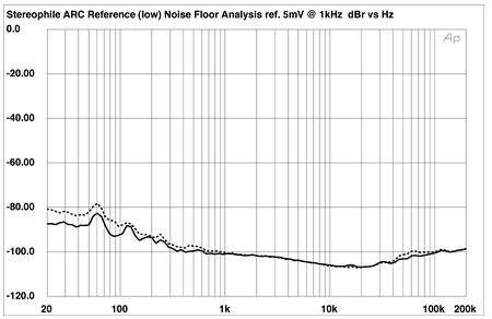 Fig.2 Audio Research Reference, Low Gain, spectrum of noise floor ref. 5mV input at 1kHz, inputs physically shorted (right channel dashed).
Despite the low measured noise floor in fig.2, what noise was present was of very low frequency, and visible as a slight "bounce" in the trace on the 'scope screen. As a result, running a THD percentage vs frequency sweep at a moderate 2.9mV/1kHz reference level into the Low Gain inputs gave what appeared to be an alarming amount of distortion (fig.3, top pair of traces). But almost all of this measured percentage is due to the contribution of the noise; the actual distortion level is much lower. Repeating the measurement at a 10x higher 29mV/1kHz reference level (fig.3, middle traces) revealed that the distortion hovered between 0.1% and 0.2% over most of the audio band, rising only in the high treble and above due to the lack of overload margin at this very high input level.
Fig.2 Audio Research Reference, Low Gain, spectrum of noise floor ref. 5mV input at 1kHz, inputs physically shorted (right channel dashed).
Despite the low measured noise floor in fig.2, what noise was present was of very low frequency, and visible as a slight "bounce" in the trace on the 'scope screen. As a result, running a THD percentage vs frequency sweep at a moderate 2.9mV/1kHz reference level into the Low Gain inputs gave what appeared to be an alarming amount of distortion (fig.3, top pair of traces). But almost all of this measured percentage is due to the contribution of the noise; the actual distortion level is much lower. Repeating the measurement at a 10x higher 29mV/1kHz reference level (fig.3, middle traces) revealed that the distortion hovered between 0.1% and 0.2% over most of the audio band, rising only in the high treble and above due to the lack of overload margin at this very high input level.
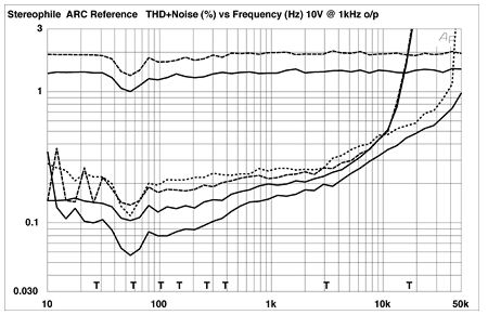 Fig.3 Audio Research Reference, THD+noise (%) vs frequency at 2.9mV at 1kHz, Low Gain (top); at 29mV at 1kHz, Low Gain (middle); and at 2.9mV at 1kHz, High Gain (bottom). (Right channel dashed.)
Surprisingly, the Reference was slightly more linear via the Jensen transformers (fig.3, bottom traces). Fig.4 shows the spectrum of a 50Hz sinewave input to the High Gain RCA jacks at a very high level (equivalent to 10V out). The highest-level harmonic appears to be the second at 100Hz, which lies at -70dB, which is appropriately low.
Fig.3 Audio Research Reference, THD+noise (%) vs frequency at 2.9mV at 1kHz, Low Gain (top); at 29mV at 1kHz, Low Gain (middle); and at 2.9mV at 1kHz, High Gain (bottom). (Right channel dashed.)
Surprisingly, the Reference was slightly more linear via the Jensen transformers (fig.3, bottom traces). Fig.4 shows the spectrum of a 50Hz sinewave input to the High Gain RCA jacks at a very high level (equivalent to 10V out). The highest-level harmonic appears to be the second at 100Hz, which lies at -70dB, which is appropriately low.
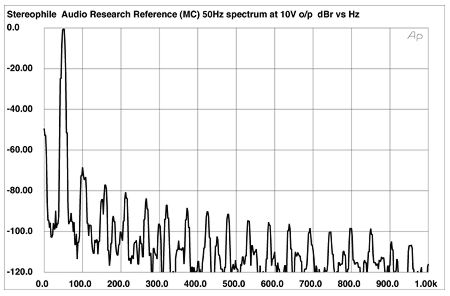 Fig.4 Audio Research Reference, High Gain, spectrum of 50Hz at 10V RMS into 100k ohms.
However, the graph is confusing: most of the peaks that can be seen are not harmonics. The very-low-level peaks that can be seen at 120Hz and 180Hz are supply-related spuriae, for example. But two peaks are apparent between 120Hz and 180Hz, one of them as expected at 150Hz, the third harmonic of the test signal at about 84dB down. The fourth harmonic, at 200Hz, can also be seen, at exactly -100dB. But there is a peak present at 162Hz, another peak 54Hz higher at 212Hz, and another at 266Hz, again a gap of 54Hz. I have no idea what these peaks are due to, but I couldn't remove them no matter how I fooled around with grounding or different physical test-gear arrangements. Color me puzzled.
Finally, figs.5 and 6 show the Reference's THD+noise percentage plotted against output voltage for the Low Gain and High Gain inputs, respectively. As I mentioned in connection with fig.3, it is actually infrasonic noise that most contributes to the measured distortion figure. That noise dominates the low-level readings is revealed by the downward-sloping nature of all the traces in these two graphs: as the signal level increases, the noise becomes a correspondingly smaller proportion of that level. The minima in these curves actually indicate the point where true distortion makes its presence known, which for the 20Hz and 1kHz traces is between 10V and 20V output!
Fig.4 Audio Research Reference, High Gain, spectrum of 50Hz at 10V RMS into 100k ohms.
However, the graph is confusing: most of the peaks that can be seen are not harmonics. The very-low-level peaks that can be seen at 120Hz and 180Hz are supply-related spuriae, for example. But two peaks are apparent between 120Hz and 180Hz, one of them as expected at 150Hz, the third harmonic of the test signal at about 84dB down. The fourth harmonic, at 200Hz, can also be seen, at exactly -100dB. But there is a peak present at 162Hz, another peak 54Hz higher at 212Hz, and another at 266Hz, again a gap of 54Hz. I have no idea what these peaks are due to, but I couldn't remove them no matter how I fooled around with grounding or different physical test-gear arrangements. Color me puzzled.
Finally, figs.5 and 6 show the Reference's THD+noise percentage plotted against output voltage for the Low Gain and High Gain inputs, respectively. As I mentioned in connection with fig.3, it is actually infrasonic noise that most contributes to the measured distortion figure. That noise dominates the low-level readings is revealed by the downward-sloping nature of all the traces in these two graphs: as the signal level increases, the noise becomes a correspondingly smaller proportion of that level. The minima in these curves actually indicate the point where true distortion makes its presence known, which for the 20Hz and 1kHz traces is between 10V and 20V output!
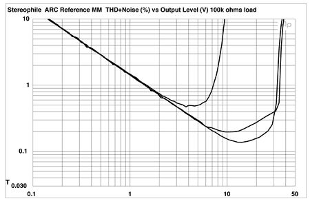 Fig.5 Audio Research Reference, Low Gain, distortion (%) vs output voltage (V) into 100k ohms with (L–R) 20kHz, 1kHz, and 20Hz signals.
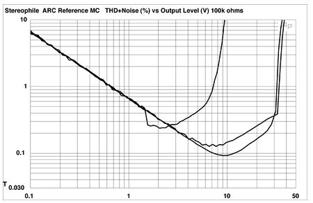 Fig.6 Audio Research Reference, High Gain, distortion (%) vs output voltage (V) into 100k ohms with (L–R) 20kHz, 1kHz, and 20Hz signals.
The lowest distortion on both inputs is achieved at 20Hz. But note that these graphs confirm that the Reference has less dynamic range at 20kHz than it does at lower frequencies. In the midrange and above, the Reference has very high overload margins. At 1kHz, the Low Gain input doesn't clip until 26.4dB above the 5mV reference level, while the High Gain input is almost as good at 25.6dB. At 20Hz, the relevant overload margins are 26dB and 24.6dB, respectively. But at 20kHz, these excellent margins drop to 12dB (Low Gain) and 14.3dB (High Gain). This will not be a problem with conventional or low-output moving-coil cartridges. Use the High Gain input for ultra-low-output models, and the Low Gain input for MCs that you suspect are "hot." But the Low Gain input is marginal for use with high-output moving-magnets, I feel. Fortunately, it's unlikely that the Reference will be used with such cartridges.—John Atkinson
Fig.6 Audio Research Reference, High Gain, distortion (%) vs output voltage (V) into 100k ohms with (L–R) 20kHz, 1kHz, and 20Hz signals.
The lowest distortion on both inputs is achieved at 20Hz. But note that these graphs confirm that the Reference has less dynamic range at 20kHz than it does at lower frequencies. In the midrange and above, the Reference has very high overload margins. At 1kHz, the Low Gain input doesn't clip until 26.4dB above the 5mV reference level, while the High Gain input is almost as good at 25.6dB. At 20Hz, the relevant overload margins are 26dB and 24.6dB, respectively. But at 20kHz, these excellent margins drop to 12dB (Low Gain) and 14.3dB (High Gain). This will not be a problem with conventional or low-output moving-coil cartridges. Use the High Gain input for ultra-low-output models, and the Low Gain input for MCs that you suspect are "hot." But the Low Gain input is marginal for use with high-output moving-magnets, I feel. Fortunately, it's unlikely that the Reference will be used with such cartridges.—John Atkinson
Fig.1 Audio Research Reference, RIAA error into 100k ohms at 5mV/1kHz input, Low Gain (top), and High Gain (bottom), driven by Audio Precision System One with 25 ohms source impedance. (Right channel dashed, 0.5dB/vertical div.)
I had some problems measuring both the preamplifier's noise levels and the crosstalk. Physically tying the inputs to ground with an RCA shorting plug gave superbly low noise levels, and channel separation that remained above 80dB over most of the audio band. Fig.2, for example, shows a spectral analysis of the Low Gain inputs' noise floors referenced to 5mV at 1kHz, this equivalent to a signal/noise ratio of 87dB measured over a wide (10Hz-500kHz) bandwidth. However, instead of shorting RCA plugs, I connected the Audio Precision's grounded outputs to the preamplifier with 6' of shielded Canare cable. Though this is theoretically identical in electrical terms, peaks in the noise now appeared at 16kHz and 32kHz. It turned out that the Reference was picking up this noise from a TV that had been left switched on, but without an input signal in the Stereophile lab. These were visible as HF hash on the oscilloscope display. I suspect that the Reference is susceptible to picking up stray RFI on its inputs. This means that while some cartridge and interconnect combinations might work well, others will be more problematic.
Fig.2 Audio Research Reference, Low Gain, spectrum of noise floor ref. 5mV input at 1kHz, inputs physically shorted (right channel dashed).
Fig.3 Audio Research Reference, THD+noise (%) vs frequency at 2.9mV at 1kHz, Low Gain (top); at 29mV at 1kHz, Low Gain (middle); and at 2.9mV at 1kHz, High Gain (bottom). (Right channel dashed.)
Surprisingly, the Reference was slightly more linear via the Jensen transformers (fig.3, bottom traces). Fig.4 shows the spectrum of a 50Hz sinewave input to the High Gain RCA jacks at a very high level (equivalent to 10V out). The highest-level harmonic appears to be the second at 100Hz, which lies at -70dB, which is appropriately low.
Fig.4 Audio Research Reference, High Gain, spectrum of 50Hz at 10V RMS into 100k ohms.
However, the graph is confusing: most of the peaks that can be seen are not harmonics. The very-low-level peaks that can be seen at 120Hz and 180Hz are supply-related spuriae, for example. But two peaks are apparent between 120Hz and 180Hz, one of them as expected at 150Hz, the third harmonic of the test signal at about 84dB down. The fourth harmonic, at 200Hz, can also be seen, at exactly -100dB. But there is a peak present at 162Hz, another peak 54Hz higher at 212Hz, and another at 266Hz, again a gap of 54Hz. I have no idea what these peaks are due to, but I couldn't remove them no matter how I fooled around with grounding or different physical test-gear arrangements. Color me puzzled.
Finally, figs.5 and 6 show the Reference's THD+noise percentage plotted against output voltage for the Low Gain and High Gain inputs, respectively. As I mentioned in connection with fig.3, it is actually infrasonic noise that most contributes to the measured distortion figure. That noise dominates the low-level readings is revealed by the downward-sloping nature of all the traces in these two graphs: as the signal level increases, the noise becomes a correspondingly smaller proportion of that level. The minima in these curves actually indicate the point where true distortion makes its presence known, which for the 20Hz and 1kHz traces is between 10V and 20V output!
Fig.5 Audio Research Reference, Low Gain, distortion (%) vs output voltage (V) into 100k ohms with (L–R) 20kHz, 1kHz, and 20Hz signals.
Fig.6 Audio Research Reference, High Gain, distortion (%) vs output voltage (V) into 100k ohms with (L–R) 20kHz, 1kHz, and 20Hz signals.
The lowest distortion on both inputs is achieved at 20Hz. But note that these graphs confirm that the Reference has less dynamic range at 20kHz than it does at lower frequencies. In the midrange and above, the Reference has very high overload margins. At 1kHz, the Low Gain input doesn't clip until 26.4dB above the 5mV reference level, while the High Gain input is almost as good at 25.6dB. At 20Hz, the relevant overload margins are 26dB and 24.6dB, respectively. But at 20kHz, these excellent margins drop to 12dB (Low Gain) and 14.3dB (High Gain). This will not be a problem with conventional or low-output moving-coil cartridges. Use the High Gain input for ultra-low-output models, and the Low Gain input for MCs that you suspect are "hot." But the Low Gain input is marginal for use with high-output moving-magnets, I feel. Fortunately, it's unlikely that the Reference will be used with such cartridges.—John Atkinson